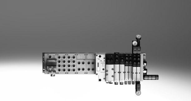
Valve terminals VTSA/VTSA-F, NPT
|
|
|
- Tamás Székely
- 5 évvel ezelőtt
- Látták:
Átírás
1

2 Key features Innovative Versatile Reliable Easy to install High-performance valves in sturdy metal housing Four valve sizes on one valve terminal Standardised from the multi-pin plug to the fieldbus connection and control block Dream team: fieldbus valve terminal suitable for electrical peripherals CPX. This means: Forward-looking internal communication system for controlling the valves and CPX modules Four valve sizes on one valve terminal without adapters Valve functions for integration in control architectures of higher categories to EN ISO Modular system offering a range of configuration options Expandable with up to 32 solenoid coils Conversions and extensions are possible at any time Manifold sub-bases can be extended using four screws, sturdy duct separation on metal support Integration of innovative function modules possible Supply plates enable a flexible air supply and variable pressure zones Reverse operation High pressure range bar, flow range l/min Wide range of valve functions Valve supply: 24 V DC or 110 V AC Sturdy and durable metal components Valves Manifold sub-bases Seals Fast troubleshooting thanks to LEDs on the valves and diagnostics via fieldbus Reliable servicing thanks to valves that can be replaced quickly and easily Manual override either non-detenting, non-detenting/detenting or covered Durable thanks to tried-and-tested piston spool valves Large and durable labelling system 100% duty cycle Assembled and inspected unit, ready for installation Reduced outlay on selection, ordering, installation and commissioning Secure mounting on wall or H-rail -H- Note The key features, valves and functions of width 65 mm are described separately in the chapter "Adaptation to width 65 mm, ISO size 3 (technology type 04)" Page Internet: Subject to change 2019/06
3 Key features Reduced downtimes: On-the-spot diagnostics via LEDs Width 18 mm, 26 mm, 42 mm and 52 mm can be combined on a single valve terminal without adapter Pneumatic interface to CPX Simple electrical connections Fieldbus connection via CPX Multi-pin plug connection with pre-assembled cable or terminal strip (Cage Clamp ) Control block via CPX AS-Interface Individual connection CPX diagnostic interface for handheld devices (channel-oriented diagnostics down to the individual valve) Quick mounting: Direct mounting using screws or H-rail Reliable operation: Manual override, detenting, non-detenting/detenting or covered Flexible: 32 valve positions/32 solenoid coils One valve series for a wide range of flow rates Functional: Large ports, flow-optimised ducts, sturdy metal thread or pre-assembled QS connections Modular: Air supply plates facilitate the creation of multiple pressure zones as well as numerous additional exhaust and supply ports Comprehensive range of valve functions Practical: Large inscription labels Safe: Valves, outputs and logic voltage can be switched off separately Equipment options Valve functions 2x 2/2-way valve, single solenoid, pneumatic spring, normally closed 2x 3/2-way valve, single solenoid Normally open Normally open, reversible Normally closed Normally closed, reversible 2x 3/2-way valve, single solenoid 1x normally open, 1x normally closed 1x normally open, 1x normally closed, reversible 5/2-way solenoid valve Single solenoid, pneumatic spring/mechanical spring Double solenoid Double solenoid with dominant signal 5/2-way solenoid valves for special functions, single solenoid Mechanical spring Switching position sensing via inductive sensors with PNP or NPN output Protection against unexpected start-up to EN 1037 Reversing 5/3-way solenoid valve Mid-position pressurised Mid-position closed Mid-position exhausted 5/3-way solenoid valve for special functions Switching position 14 is retained (switching position 14 is retained in the event of an emergency-off application/power failure), there is no spring return on switching position 12 Only for valve terminal (plug-in) Mid-position exhausted or midposition 1 2, 4 5 Switching position 14 is retained Pneumatic spring return 5/3-way solenoid valve for special functions Switching position 12 is retained (switching position 12 is retained in the event of an emergency-off application/power failure), there is no spring return on switching position 14. Only for valve terminal (plug-in) Mid-position exhausted or midposition 1 4, 2 3 Switching position 12 is retained Pneumatic spring return Soft-start valve for slow and safe pressure build-up High degree of safety Sensor function provides feedback on switching operation -H- Note The key features, valves and functions of width 65 mm are described separately in the chapter Adaptation to width 65 mm, ISO size 3 (technology type 04) Page /06 Subject to change Internet: 3
4 Key features Special features Individual valve on individual sub-base up to width 52 mm Valve terminal with fieldbus connection and electrical peripherals Plug-in Electrical connection via standardised 4-pin M12 plug or via 4-pin spring-loaded terminal for configuration by the user Available with internal/external pilot air supply Square plug or plug-in, with integrated piston position sensing Electrical connection to DIN EN type C (square plug) or For configuration by the user via 4-pin spring-loaded terminal or Cable with open end CPX terminal Max. 32 valve positions/ max. 32 solenoid coils Any compressed air supply Any number of pressure zones Valve terminal with individual connection Valve terminal with multi-pin plug connection AS-Interface Combinable Max. 20 valve positions/ max. 20 solenoid coils Any compressed air supply Any number of pressure zones Max. 32 valve positions/ max. 32 solenoid coils Parallel modular valve linking Any compressed air supply Any number of pressure zones 1 to 8 valve positions/ max. 8 solenoid coils Soft-start valve for slow and safe pressure build-up Valve width 18 mm: flow rate of VTSA up to 550 l/min, VTSA-F up to 700 l/min Valve width 26 mm: flow rate of VTSA up to 1100 l/min, VTSA-F up to 1350 l/min Valve width 42 mm: flow rate of VTSA up to 1300 l/min, VTSA-F up to 1860 l/min Valve width 52 mm: flow rate up to 2900 l/min Widths 18 mm, 26 mm, 42 mm, 52 mm and 65 mm can be combined on a single valve terminal (using an adapter) -H- Note Valve terminal VTSA complies with ISO in width 18 and 26 mm and With ISO in size 42 and 52 mm Valve terminal configurator A valve terminal configurator is available to help you select a suitable VTSA/VTSA-F valve terminal. This makes it much easier to order the right product. Internet: The valve terminals are fully assembled according to your order specification and are individually checked. This reduces assembly and installation time to a minimum. Order a valve terminal VTSA using the order code: Ordering system for VTSA Internet: vtsa Order a valve terminal VTSA-F using the order code: Ordering system for VTSA-F Internet: vtsa-f Ordering system for CPX Internet: cpx Ordering system for CPX Internet: cpx Ordering data Product options Configurable product This product and all its options can be ordered using the configurator. The configurator can be found under Products on the DVD or at Part No. Type VTSA-MP-NPT VTSA-F-MP-NPT VTSA-FB-NPT VTSA-F-FB-NPT VTSA-ASI-NPT VTSA-F-ASI-NPT 4 Internet: Subject to change 2019/06
5 Key features Individual pneumatic connection Valves on individual sub-bases up to width 52 mm can be used for actuators further away from the valve terminal. The electrical connection is established either via a standardised 4-pin M12 plug, 24 V DC (EN ), 4-pin springloaded terminal or a cable with open end, 24 V DC or 110 V AC, which are configured by the user. Valve terminal with individual electrical connection Control signals from the controller to the valve terminal are transmitted via an individual connecting cable. The valve terminal can be equipped with max. 20 valves and max. 20 solenoid coils. The electrical connection is established via a 5-pin M12 plug, 24 V DC. Valve terminal with multi-pin plug connection Control signals from the controller to the valve terminal are transmitted via a pre-assembled multi-wire cable or a multi-pin plug connection assembled by the user (spring-loaded terminal), which substantially reduces installation time. The valve terminal can be equipped with max. 32 valves and max. 32 solenoid coils. Versions Multi-pin plug connection with terminal strip (spring-loaded terminal), 24 V DC or 110 V AC Pre-assembled connecting cable, 24 V DC Sub-D plug connector for assembly by the user, 37-pin Round plug connector M23, 19-pin, 24 V DC AS-Interface connection A special feature of the AS-Interface is the simultaneous transmission of data and supply power via a two-wire cable. The encoded cable profile prevents connection with incorrect polarity. The valve terminal with AS-Interface is available in the following versions: With one to eight modular valve positions (max. 8 solenoid coils). This corresponds to 1 to 8 VSVA valves. With all available valve functions. The connection technology used for the inputs can be selected as with CPX: M8, M12, quick connection, Sub-D, spring-loaded terminal (terminals to IP20). Additional information Internet: as-interface -H- Note The valve terminal VTSA/VTSA-F with AS-Interface connection is based on the same electrical interlinking module as the valve terminal with multipin plug connection. This means it is possible to convert a valve terminal with multi-pin plug connection using an AS-Interface module ( Page 131). The technical specifications of the AS-Interface system must be observed in this case. Page 58 Internet: as-interface 2019/06 Subject to change Internet: 5
6 Key features Valve terminal with fieldbus connection from the CPX system An integrated fieldbus node manages the communication connection with a higher-order PLC. This enables a space-saving pneumatic and electronic solution. Valve terminals with fieldbus interfaces from the CPX system can be configured with up to 16 manifold sub-bases. With 2 solenoid coils per connection, up to 32 solenoid coils can thus be actuated. Versions PROFIBUS INTERBUS DeviceNet CANopen CC-Link EtherNet/IP EtherCAT Modbus TCP PROFINET POWERLINK Sercos III Internet: cpx Valve terminal with control block connection from the CPX system A controller integrated in the Festo valve terminal enables the construction of stand-alone control units with protection to IP65 without a control cabinet thanks to two different operating modes. In the slave operating mode, these valve terminals can be used for intelligent preprocessing and are therefore ideal modules for designs using decentralised intelligence. In the master operating mode, terminal groups can be designed with many options and functions that can autonomously control a medium-sized machine/system. Internet: cpx CP string extension from the CPX system The optional CP string extension enables additional valve terminals and I/O modules to be connected to the fieldbus node of the CPX terminal on up to 4 CP strings. Different input and output modules as well as MPA-S and CPV valve terminals can be connected. The maximum length of the CP string extension is 10 metres, which means that the extension modules can be mounted directly on-site. All the required electrical signals are transmitted via the CP cable, which in turn means that no further installation is needed on the extension module. One CP string offers: 32 input signals 32 output signals for output modules 24 V DC or solenoid coils Logic and sensor supply for the input modules Load voltage supply for the valve terminals Logic supply for the output module Internet: ctec 6 Internet: Subject to change 2019/06
7 Key features Valves Solenoid valve with switching position sensing, width 18 mm, 26 mm The 5/2-way single solenoid valve with spring return in width 26 mm features switching position sensing. The normal position of the piston spool valve is monitored. Designed as a plug-in or individual connection valve with pilot valves to ISO and square plug type C. This valve is not a safety device in accordance with the Machinery Directive 2006/42/EC. It is suitable for use in safety-related parts of control systems to EN ISO Page 134 Control block with safety function, width 26 mm 5/2-way solenoid valve These valves are used for special applications, for example for: Protecting against unexpected start-up Safe reversing Drives in manually loaded devices This control block is suitable for use as a press safety valve to EN 962. This valve is a safety device in accordance with the Machinery Directive 2006/42/EC. Page 144 Pilot air switching valve, width 18 mm, 26 mm The pilot air switching valve is a combination of a 5/2-way solenoid valve with switching position sensing and the intermediate plate VABF-S4- -S. It enables the pilot air supply to be verifiably switched on and off (sensor function) from duct 1 to 14 for the entire pressure zone or valve terminal. The piston position sensing feature is realised by means of an inductive PNP proximity sensor with cable and pushin connector in the size M12x1 to EN This valve is not a safety device in accordance with the Machinery Directive 2006/42/EC. It is suitable for use in safety-related parts of control systems to EN ISO Page 151 -H- Note The pilot air switching valve can only be operated on the valve terminal VTSA/VTSA-F in combination with a right-hand end plate for external pilot air type VABE-S6-1RZ-. Port 14 on the right-hand end plate must be sealed for this. Soft-start valve, module width 43 mm The soft-start valve is separately electrically actuated, independently of the multi-pin plug, AS-Interface or fieldbus connection, via a 4-pin plug to ISO or optionally via an M12 adapter. The valve can optionally be ordered with a sensor that monitors switching of the soft-start valve. The soft-start valve can supply the valve terminal or one or more pressure zones with supply air. The pressure build-up for each pressure zone is optimised for the application directly at the valve terminal by setting the switch-over pressure and the filling time. A maximum of 5 soft-start valves can be integrated on one valve terminal in this way. Page /06 Subject to change Internet: 7
8 Key features Valves Vacuum block, module width 53 mm 5/3-way solenoid valve, with switching position 12 retained. The vacuum block is screwed to a manifold sub-base for 2 valve positions, width 26 mm, and integrated into the valve terminal VTSA/VTSA-F. The vacuum block is supplied with electricity and the vacuum is sensed via a standardised 4-pin M12 plug. The vacuum block is used in conjunction with a suction gripper to receive, hold and place components. Placing is realised by means of an adjustable ejector pulse. The vacuum block is equipped with an air-saving function. In the absence of electric or pneumatic supply, the valve reverts to switching position 12 "create vacuum". Page 170 5/3-way solenoid valve for special functions For holding, blocking a movement (mechanically) 5/3-way solenoid valve for special functions; port 2 is pressurised, port 4 vented. Switching position 14 is retained (code SA). 5/3-way solenoid valve for special functions; port 2 is pressurised, port 4 vented. Switching position 12 is retained (code SE). Possible applications: Using lifting cylinders Using rotary cylinders Possible applications: Using lifting cylinders Using rotary cylinders For pressureless switching, self-latching loop, pneumatic operation 5/3-way solenoid valve for special functions (3 phases). Mid-position is exhausted. Switching position 14 is retained. 5/3-way solenoid valve for special functions (3 phases). Mid-position is exhausted. Switching position 12 is retained. Possible applications: Pneumatic manual clamps for devices (inserting stations) Possible applications: Pneumatic manual clamps for devices (inserting stations) 8 Internet: Subject to change 2019/06
9 Peripherals Modular pneumatic peripherals The modular design of the valve terminal VTSA/VTSA-F enables maximum flexibility right from the planning stage and offers maximum ease of service in operation. The system consists of manifold sub-bases and valves. The manifold sub-bases are screwed together and thus form the support system for the valves. Inside the manifold sub-bases are the ducts for supplying compressed air to and exhausting from the valve terminal as well as the working ports for the pneumatic cylinders for each valve. Each manifold sub-base is connected to the next using four screws. Individual valve terminal sections can be isolated and further blocks easily inserted by loosening these screws. This ensures that the valve terminal can be rapidly and reliably extended. Basic system modularity Valve modularity Vertical stacking modularity -H- Note See also "Adaptation to width 65 mm, ISO size 3 (technology type 04)" page /06 Subject to change Internet: 9
10 Peripherals Modular electrical peripherals The manner in which the valves are actuated differs according to whether you are using a multi-pin terminal or fieldbus terminal. The VTSA/VTSA-F with CPX interface is based on the internal bus system of the CPX and uses this communication system for all solenoid coils and a range of electrical input and output functions. Parallel linking enables the following: Transmission of switching information Compact design Position-based diagnostics Separate voltage supply for valves Flexible conversion without address shifting Option of CP interface CPX-CEC as stand-alone controller with access via Ethernet and web server Transmission of status, parameter and diagnostic data Internet: cpx VTSA/VTSA-F with electrical peripherals CPX Modularity with electrical peripherals CPX CPX terminal in metal design The CPX modules in metal design are mechanically connected to one another using an angled fitting. The CPX terminal can thus be expanded at any time. -H- Note The CPX connection blocks are also available in a metal design. This means a complete solution in a sturdy metal design can be selected for applications of the valve terminal VTSA/VTSA-F in welding environments. 10 Internet: Subject to change 2019/06
11 Peripherals Pneumatic components Valve terminal widths Order code for VTSA: 44E- for the electrical components 44P- for the pneumatic components Order code for VTSA-F: 45E- for the electrical components 45P- for the pneumatic components Regardless of the type of actuation (e.g. multi-pin plug, fieldbus, etc.), valve terminals VTSA/VTSA-F in the widths 18 mm 26 mm 42 mm 52 mm can be combined without adapters. This enables a flow range of 400 l/min to 2,900 l/min in the case of VTSA and 700 l/min to 2,900 l/min in the case of VTSA-F to be covered on one valve terminal. A wide range of valve functions and vertical stacking components are available for all widths. Valves with a width of 65 mm can be mixed with other widths. However, these are only configured after the adapter plate VABA and are thus always at the end of the valve terminal configuration. See "Adaptation to width 65 mm, ISO size 3 (technology type 04)" page Description 1 Valve Width 18 mm Valve Width 26 mm Valve Width 42 mm Valve Width 52 mm Multi-pin plug connection Via multi-pin cable, 24 V DC Inscription labels For manifold sub-base, sub-base, 90 connection plate 133 Page/Internet 2019/06 Subject to change Internet: 11
12 Peripherals Pneumatic components Individual sub-base, width 18 mm, ISO Order code: Using individual part numbers Individual sub-bases can be equipped with any valve. Width 18 mm with spring-loaded terminal or cable (open end) aj 2 1 aa Description 1 Fitting 1/8 NPT for air/exhaust ports (1, 3, 5) and working ports (2, 4) Silencer U-1/8-B-NPT for exhaust ports (3, 5) Electrical connection Spring-loaded terminal, cable (open end) 4 Valve VSVA Width 18 mm 90 5 Manual override Non-detenting/detenting, per solenoid coil 6 Cover cap, heavy duty For manual override, non-detenting heavy duty, detenting via accessory Cover cap, coded For non-detenting manual override (limited function) Cover cap, covered MO covered by cover cap operation of MO prevented Inscription label holder For valves 133 aj Individual sub-base For valve VSVA 204 aa Inscription label holder For manifold block 133 Page/Internet 12 Internet: Subject to change 2019/06
13 Peripherals Pneumatic components Individual sub-base, width 26 mm, ISO With spring-loaded terminal or cable (open end) aj 2 1 aa Description 1 Fitting 1/4 NPT for air/exhaust ports (1, 3, 5) and working ports (2, 4) Silencer U-1/4-B-NPT for exhaust ports (3, 5) Electrical connection Spring-loaded terminal, cable (open end) 4 Valve VSVA Width 26 mm 99 5 Manual override Non-detenting/detenting, per solenoid coil 6 Cover cap, heavy duty For manual override, non-detenting heavy duty, detenting via accessory Cover cap, coded For non-detenting manual override (limited function) Cover cap, covered MO covered by cover cap operation of MO prevented Inscription label holder For valves 133 aj Individual sub-base For valve VSVA 204 aa Inscription label holder For manifold block 133 Page/Internet 2019/06 Subject to change Internet: 13
14 Peripherals Pneumatic components Individual sub-base, width 42 mm, ISO With spring-loaded terminal or cable (open end) aj 2 1 aa Description 1 Fitting 3/8" NPT for air/exhaust ports (1, 3, 5) and working ports (2, 4) Silencer U-3/8-B-NPT for exhaust ports (3, 5) Electrical connection Spring-loaded terminal, cable (open end) 4 Valve VSVA Width 42 mm Manual override Non-detenting/detenting, per solenoid coil 6 Cover cap, heavy duty For manual override, non-detenting heavy duty, detenting via accessory Cover cap, coded For non-detenting manual override (limited function) Cover cap, covered MO covered by cover cap operation of MO prevented Inscription label holder For valves 133 aj Individual sub-base For valve VSVA 204 aa Inscription label holder For manifold block 133 Page/Internet 14 Internet: Subject to change 2019/06
15 Peripherals Pneumatic components Individual sub-base, width 52 mm, ISO With spring-loaded terminal or cable (open end) aj 2 1 aa Description 1 Fitting 3/8" NPT for air/exhaust ports (1, 3, 5) and working ports (2, 4) Silencer U-3/8-B-NPT for exhaust ports (3, 5) Electrical connection Spring-loaded terminal, cable (open end) 4 Valve VSVA Width 52 mm Manual override Non-detenting/detenting, per solenoid coil 6 Cover cap, heavy duty For manual override, non-detenting heavy duty, detenting via accessory Cover cap, coded For non-detenting manual override (limited function) Cover cap, covered MO covered by cover cap operation of MO prevented Inscription label holder For valves 133 aj Individual sub-base For valve VSVA 204 aa Inscription label holder For manifold block 133 Page/Internet 2019/06 Subject to change Internet: 15
16 Peripherals Pneumatic components Valve terminal pneumatics The manifold sub-bases for valves with a width of 18 or 26 mm are either prepared for 2 single solenoid valves or 2 double solenoid valves The manifold sub-bases for valves with a width of 42 or 52 mm are suitable for 1 single solenoid valve or 1 double solenoid valve. Double solenoid valve positions can be equipped with any valve or a blanking plate. Single solenoid valve positions can only be equipped with single solenoid valves or a blanking plate. 9 aj aa ab 7 8 bc ae ad ac af 2 ag ai ah bj ai ag ba ai bb 16 Internet: Subject to change 2019/06
17 Peripherals Pneumatic components Valve terminal pneumatics Description Page/Internet 1 Exhaust port cover For ducted exhaust air (ports 3 and 5 combined) Duct separation/seal Manifold sub-base For soft-start valve Soft-start valve For slow and safe pressure build-up Plug socket Flow control plate Pressure regulator plate Valve Width 18 mm or 26 mm 90, 99 9 Cover cap, heavy duty For manual override, non-detenting heavy duty, detenting via accessory 130 aj Cover cap, coded For non-detenting manual override (limited function) 130 aa Cover cap, covered MO covered by cover cap operation of MO prevented 130 ab Inscription label holder For valve 133 ac Blanking plate For unused valve position (vacant position) 130 ad Valve Width 42 mm or 52 mm 108, 116 ae End plate with pilot air selector 124 af Blanking plug 206 ag Manifold sub-base VTSA For valves with a width of 42 mm or 52 mm 124 ag Manifold sub-base VTSA-F For valves with a width of 42 mm or 52 mm 124 ah Manifold sub-base VTSA For valves with a width of 18 mm or 26 mm 124 ah Manifold sub-base VTSA-F For valves with a width of 18 mm or 26 mm 124 ai Fittings 205 bj Silencer 206 ba Inscription label holder For manifold sub-base, sub-base, 90 connection plate 133 bb Supply plate 125 bc Control element Regulator knobs in different versions 37 -H- Note Special applications for the valve terminal, such as: Solenoid valve with switching position sensing Control block with safety function Pilot air switching valve Soft-start valve Vacuum block are listed after Accessories General 2019/06 Subject to change Internet: 17
18 Peripherals Electrical components Valve terminal with individual electrical connection Order code for VTSA: 44E- for the electrical components 44P- for the pneumatic components Order code for VTSA-F: 45E- for the electrical components 45P- for the pneumatic components Valve terminals VTSA/VTSA-F with individual electrical connection can be expanded with up to 20 valves with max. 20 solenoid coils. The manifold sub-bases for valves with a width of 18 or 26 mm are either prepared for 2 single solenoid valves or 2 double solenoid valves and the manifold sub-bases for valves with a width of 42, 52 and 65 mm are prepared for 1 single solenoid valve or 1 double solenoid valve. Double solenoid valve positions can be equipped with any valve or a blanking plate. Single solenoid valve positions can only be equipped with single solenoid valves or a blanking plate. The electrical connection is established via a 5-pin M12 plug (24 V DC). Valves with a width of 65 mm cannot be mixed with other widths these are always at the end of the valve terminal configuration. See "Adaptation to width 65 mm, ISO size 3 (technology type 04)" Page Description 1 Cover For individual connection Multi-pin plug connection Individual connection with M12, 10-way or 6-way (including cover) 131 Page/Internet 18 Internet: Subject to change 2019/06
19 Peripherals Electrical components Valve terminal with electrical multi-pin plug connection Order code for VTSA: 44E- for the electrical components 44P- for the pneumatic components Order code for VTSA-F: 45E- for the electrical components 45P- for the pneumatic components Valve terminals VTSA/VTSA-F with electrical multi-pin plug connection can be expanded with up to 32 valves with max. 32 solenoid coils. The manifold sub-bases for valves with a width of 18 or 26 mm are prepared for 2 single solenoid valves or 2 double solenoid valves and the manifold sub-bases for valves with a width of 42, 52 and 65 mm are prepared for 1 single solenoid valve or 1 double solenoid valve. Double solenoid valve positions can be equipped with any valve or a blanking plate. Single solenoid valve positions can only be equipped with single solenoid valves or a blanking plate. The following multi-pin plug connections to IP65 are available: 37-pin Sub-D connection (24 V DC): the connecting cable can be ordered in lengths of 2.5 m, 5 m and 10 m for max. 8, 22 or 32 solenoid coils respectively. Terminal strip (24 V DC or 110 V AC) 19-pin round connector (24 V DC) Valves with a width of 65 mm cannot be mixed with other widths these are always at the end of the valve terminal configuration. See "Adaptation to width 65 mm, ISO size 3 (technology type 04)" Page Description 1 Inscription labels Large, for multi-pin plug connection 2 Multi-pin cable Multi-pin plug connection Via M23 round plug connection, 24 V DC Multi-pin plug connection Via terminal strip (Cage Clamp ), 24 V DC or 110 V AC Multi-pin plug connection Via multi-pin cable, 24 V DC 131 Page/Internet 2019/06 Subject to change Internet: 19
20 Peripherals Electrical components Valve terminal with AS-Interface connection Order code for VTSA: 52E- for the electrical components 44P- for the pneumatic components Order code for VTSA-F: 52E- for the electrical components 45P- for the pneumatic components Valve terminals VTSA/VTSA-F with AS- Interface connection can be expanded with up to 8 valves with max. 8 solenoid coils. The manifold sub-bases for valves with a width of 18 or 26 mm are either prepared for 2 single solenoid valves or 2 double solenoid valves and the manifold sub-bases for valves with a width of 42, 52 and 65 mm are prepared for 1 single solenoid valve or 1 double solenoid valve. Double solenoid valve positions can be equipped with any valve or a blanking plate. Single solenoid valve positions can only be equipped with single solenoid valves or a blanking plate. Valves with a width of 65 mm cannot be mixed with other widths these are always at the end of the valve terminal configuration. See "Adaptation to width 65 mm, ISO size 3 (technology type 04)" Page Description 1 Multi-pin plug connection Can be ordered together with the AS-Interface module as an electrical connection for AS-Interface 2 Manifold block for AS-Interface AS-Interface module 131 Page/Internet Internet: Subject to change 2019/06
21 Peripherals Electrical components Valve terminal with fieldbus connection, control block (electrical peripherals CPX) Order code: 50E- for the electrical peripherals, plastic manifold module 51E- for the electrical peripherals, metal manifold module 53E- for the electrical peripherals, for control cabinet installation For VTSA: 44P- for the pneumatic components For VTSA-F: 45P- for the pneumatic components Valve terminals VTSA/VTSA-F with fieldbus interface can be expanded with up to 32 valves with max. 32 solenoid coils. The manifold sub-bases for valves with a width of 18 or 26 mm are either prepared for 2 single solenoid valves or 2 double solenoid valves and the manifold sub-bases for valves with a width of 42, 52 and 65 mm are prepared for 1 single solenoid valve or 1 double solenoid valve. Double solenoid valve positions can be equipped with any valve or a blanking plate. Single solenoid valve positions can only be equipped with single solenoid valves or a blanking plate. Each valve position can be equipped with any valve or a blanking plate. The rules for CPX apply to the equipment that can be used in combination with the electrical peripherals CPX. In general: Max. 10 electrical modules Digital inputs/outputs Analogue inputs/outputs Parameterisation of inputs and outputs Integrated convenient diagnostic system Preventive maintenance concepts Valves with a width of 65 mm cannot be mixed with other widths these are always at the end of the valve terminal configuration. See "Adaptation to width 65 mm, ISO size 3 (technology type 04)" Page Description 1 Inscription labels Large, for pneumatic interface CPX 2 Pneumatic interface Fieldbus interface cpx Page/Internet 2019/06 Subject to change Internet: 21
22 Peripherals Electrical components Valve terminal with fieldbus/multi-pin plug connection and individually electrically actuated valve In applications with specific emergency off conditions, it may be necessary to switch one or more valves separately from the valve terminal controller. Standard valves (VSVA) with individual electrical connection (round or square plug) are mounted on the valve terminal to this end. In order for protection class IP65 to be achieved, the functionless opening in the sub-base for the electrical connection must be sealed. A sealing cap is available for the 18 mm and 26 mm widths. With manifold or individual subbases, valves with width 42 mm and 52 mm must be used with a seal to comply with the IP protection class (see page 130). For central control of the valve terminal via a multi-pin plug or fieldbus connection, the valve position occupied in this way acts like a vacant position, i.e. the assigned address in the fieldbus node or the corresponding connection in the multi-pin plug connection is occupied Description Page/Internet 1 Sealing cap For sealing the electrical connection on the sub-base Valve Width 18 mm or width 26 mm valves vsva 3 Connecting cable valves vsva 4 Seal For ensuring the IP protection class (with width 42 mm and 52 mm) Valve Width 42 mm or width 52 mm valves vsva -H- Note Standard valves VSVA can be used for valve terminal allocation. A vacant position must be provided for this in the valve terminal configurator. The corresponding standard valve VSVA can be ordered on the Internet at: vsva 22 Internet: Subject to change 2019/06
23 Key features Pneumatic components Manifold sub-base VTSA/VTSA-F is based on a modular system which consists of manifold sub-bases and valves. The VTSA-F manifold sub-bases are designed to optimise flow. Manifold sub-bases are available for valve widths 18 mm and 26 mm in a double grid, i.e. two valves per manifold sub-base. For valves with a width of 42 mm or 52 mm, there are manifold sub-bases with one valve per sub-base. The manifold sub-base contains a duct seal and an electrical interlinking module. They can be freely mixed within a valve terminal. The manifold sub-bases are screwed together and thus form the support system for the valves. Inside the manifold sub-bases are the ducts for supplying compressed air to and exhausting from the valve terminal as well as the working ports for the pneumatic cylinders for each valve. Each manifold subbase is connected to the next using four screws. Individual valve terminal sections can be isolated and further manifold sub-bases inserted by loosening these screws. This ensures that the valve terminal can be rapidly and reliably extended. See also "Adaptation to width 65 mm, ISO size 3 (technology type 04)" Page 176 Port patterns on the manifold sub-base for one valve position Width 18 mm Width 26 mm Width 42 mm Width 52 mm -H- Note The illustrations shown depict a schematic representation of the pneumatic ISO port patterns. The port patterns on the valve terminal VTSA-F do not correspond to the ISO standard. 2019/06 Subject to change Internet: 23
24 Key features Pneumatic components Manifold sub-base variants with QS fitting, valve terminal VTSA Code Type Width No. of valve 18 mm 26 mm 42 mm 52 mm positions (solenoid coils) 1) Code M large Manifold sub-base for double solenoid valves A VABV-S4-2S-N18-2T2 Working ports (2, 4) Code N small 2 (4) QB-1/8-5/16-U AK QB-1/8-1/4-U B VABV-S4-1S-N14-2T2 2 (4) QB-1/4-3/8-U BK QB-1/4-5/16-U C VABV-S2-1S-N38-T2 1 (2) QB-3/8-1/2-U CK QB-3/8-3/8-U D VABV-S2-2S-N12-T2 1 (2) QB-1/2-1/2-U DK Manifold sub-base for single solenoid valves E VABV-S4-2S-N18-2T1 2 (2) QB-1/8-5/16-U EK QB-1/8-1/4-U F VABV-S4-1S-N14-2T1 2 (2) QB-1/4-3/8-U FK QB-1/4-5/16-U G VABV-S2-1S-N38-T1 1 (1) QB-3/8-1/2-U GK QB-3/8-3/8-U H VABV-S2-2S-N12-T1 1 (1) QB-1/2-1/2-U HK 1) Value in brackets is max. number of solenoid coils that can be controlled 24 Internet: Subject to change 2019/06
25 Key features Pneumatic components Manifold sub-base variants with QS fitting, valve terminal VTSA-F Code Type Width No. of valve 18 mm 26 mm 42 mm 52 mm positions (solenoid coils) 1) Code M large Manifold sub-base for double solenoid valves A VABV-S4-2HS-N18-2T2 Working ports (2, 4) Code N small 2 (4) QB-1/8-5/16-U AK QB-1/8-1/4-U B VABV-S4-1HS-N14-2T2 2 (4) QB-1/4-3/8-U BK QB-1/4-5/16-U C VABV-S2-1HS-N38-T2 1 (2) QB-3/8-1/2-U CK QB-3/8-3/8-U D VABV-S2-2S-N12-T2 1 (2) QB-1/2-1/2-U DK Manifold sub-base for single solenoid valves E VABV-S4-2HS-N18-2T1 2 (2) QB-1/8-5/16-U EK QB-1/8-1/4-U F VABV-S4-1HS-N14-2T1 2 (2) QB-1/4-3/8-U FK QB-1/4-5/16-U G VABV-S2-1HS-N38-T1 1 (1) QB-3/8-1/2-U GK QB-3/8-3/8-U H VABV-S2-2S-N12-T1 1 (1) QB-1/2-1/2-U HK 1) Value in brackets is max. number of solenoid coils that can be controlled 90 connection plate for working ports 2 and 4 with NPT thread Code Type Width Ports Working ports (2, 4) on the mm 26 mm 42 mm 52 mm connection plate P VABF-S4- -A2G2-N 2 and 4 1/8" NPT 1/4" NPT 3/8" NPT 1/2" NPT 2019/06 Subject to change Internet: 25
26 Key features Pneumatic components Sub-base valve All valves are fitted with piston spool and patented sealing system, which ensures efficient sealing, a broad operating pressure range and long service life. Sub-base valves can be quickly replaced since the tubing connections remain on the manifold sub-base. Irrespective of the valve function there are sub-base valves with one solenoid coil (single solenoid) or with two solenoid coils for double solenoid or double valve functions. Reverse/vacuum operation Select reverse operation (code Z) if you wish to operate an actuator (cylinder) with different pressures for the forward and return stroke. Please note that the valves must then be operated via a separate pressure zone. The reversible 3/2-way solenoid valves are also suitable for vacuum operation. Reverse operation is only possible in pressure zones with external pilot air supply. -H- Note If a pressure zone is in reverse operation, supply air is connected to port 3/5 and exhausting takes place at port 1 at all valve positions in this pressure zone. Reversible pressure regulators cannot be selected when a pressure zone is in reverse operation. With reversible pressure regulators, only the valve at this position is in reverse operation. When using 5/3-way valves in reverse operation, the mid-position function switches from exhausted to pressurised and vice versa. Blanking plate Plate without valve function for reserving valve positions on a valve terminal. Valve and blanking plates are attached to the manifold sub-base using screws. Design Valve replacement The valves are attached to the metal manifold sub-base using two or four screws, which means that they can be Extension easily replaced. The mechanical robustness of the manifold sub-base guarantees efficient long-term sealing. Vacant positions can be fitted with valves at a later date. The dimensions, mounting points and existing pneumatic installations remain unchanged during this process. For more information and technical data on expansion, refer to the user documentation: Internet: P.BE-VTSA Internet: Subject to change 2019/06
27 Key features Pneumatic components Valve function Terminal code Circuit symbol Valve code Width 18 mm 26 mm 42 mm 52 mm Description VC T22C 2x 2/2-way valve, single solenoid Normally closed Pneumatic spring return VV T22CV 2x 2/2-way valve, single solenoid Reverse operation Normally closed Pneumatic spring return Vacuum operation possible at 3 and 5 N T32U 2x 3/2-way valve, single solenoid Normally open Pneumatic spring return Operating pressure 3 bar K T32C 2x 3/2-way valve, single solenoid Normally closed Pneumatic spring return Operating pressure 3 bar H T32H 2x 3/2-way valve, single solenoid Normal position 1x closed 1x open Pneumatic spring return Operating pressure 3 bar P T32F 2x 3/2-way valve, single solenoid Reverse operation only Normally open Pneumatic spring return Q T32N 2x 3/2-way valve, single solenoid Reverse operation only Normally closed Pneumatic spring return R T32W 2x 3/2-way valve, single solenoid Reverse operation only Normal position 1x closed 1x open Pneumatic spring return -H- Note A filter must be installed upstream of valves operated in vacuum mode. This prevents any foreign matter in the intake air getting into the valve (e.g. when operating a suction cup). 2019/06 Subject to change Internet: 27
28 Key features Pneumatic components Valve function Terminal code Circuit symbol Valve code Width 18 mm 26 mm 42 mm 52 mm Description M M52-A 5/2-way valve, single solenoid Reverse operation Pneumatic spring return O M52-M 5/2-way valve, single solenoid Reverse operation Mechanical spring return J B52 5/2-way valve, double solenoid D D52 5/2-way valve, double solenoid Dominant signal at port 14 on the control side SO SQ SS M52-M 5/2-way valve2), single solenoid, as plug-in or via pilot valve with pneumatic interface to ISO See also special valve function in the separate chapter "Solenoid valve with switching position sensing" page 140 SO SQ SS M52-M 5/2-way valve2), single solenoid, as plug-in or via pilot valve with pneumatic interface to ISO See also special valve function in the separate chapter "Solenoid valve with switching position sensing" page 140 SP SN T52-M 2x 5/2-way valve, single solenoid, with switching position sensing, pneumatically linked via two channels as special valve function control block with safety function page 167 B P53U 5/3-way solenoid valve Mid-position pressurised 1) Mechanical spring return G P53C 5/3-way solenoid valve Mid-position closed 1) Mechanical spring return E P53E 5/3-way solenoid valve Mid-position exhausted 1) Mechanical spring return 1) If neither solenoid coil is energised, the valve moves to its mid-position by means of a mechanical spring. If the two coils are permanently energised one after the other, the valve remains in the switching position of the coil that was activated first. 2) The symbol represents a valve with a proximity sensor with a switching output signal, in the illustration an N/O contact. In accordance with ISO , this symbol applies to both N/O contacts and N/C contacts. The switching element function of all sensors used here is an N/C contact. 28 Internet: Subject to change 2019/06
29 Key features Pneumatic components Valve function Terminal code Circuit symbol Valve code Width 18 mm 26 mm 42 mm 52 mm Description SA P53ED SB P53AD SD P53BD SE P53EP VG P53F VB L 5/3-way solenoid valve, for special functions through default position in switching position 14 Pressureless switching, self-latching loop, pneumatic operation Mid-position exhausted, switching position 14 is retained Mechanical spring return 5/3-way solenoid valve, for special functions through default position in switching position 14 Holding, blocking a movement (mechanically) Mid-position: port 2 pressurised, port 4 exhausted, switching position 14 is retained Mechanical spring return 5/3-way solenoid valve, for special functions through default position in switching position 14 Holding, blocking a movement (mechanically) Mid-position: port 4 pressurised, port 2 exhausted, switching position 14 is retained Mechanical spring return 5/3-way solenoid valve, for special functions through default position in switching position 12 Pressureless switching, self-latching loop, pneumatic operation Mid-position exhausted, switching position 12 is retained Mechanical spring return 5/3-way solenoid valve Positioning Mid-position: port 2 pressurised, port 4 closed 1) Mechanical spring return Vacuum generator with ejector pulse and adjustable air saving function (plate for 2 valve positions, sensor SDE3 with display and M12 connection) For valve terminal only: Blanking plate for vacant valve position 1) If neither solenoid coil is energised, the valve moves to its mid-position by means of a mechanical spring. If the two coils are permanently energised one after the other, the valve remains in the switching position of the coil that was activated first. 2019/06 Subject to change Internet: 29
30 Key features Pneumatic components Vertical stacking Additional function units can be added to each valve position between the sub-base (manifold sub-base) and the valve. These functions are known as vertical stacking modules and enable special functioning or control of an individual valve position. Combinations of several valve sizes on one valve terminal are possible. -H- Note Certain combinations are not recommended due to the design of the individual vertical stacking components. Vertical stacking components 1 The following component sequence is recommended for valve positions with vertical stacking: 1 Valve VSVA 2 Pressure regulator plate 3 Flow control plate 4 Vertical pressure shut-off plate 5 Vertical supply plate 6 Manifold sub-base Internet: Subject to change 2019/06
31 Key features Pneumatic components Vertical stacking Pressure regulator plate An adjustable pressure regulator can be installed between the sub-base (manifold sub-base) and the valve in order to control the force of the triggered actuator. This pressure regulator maintains an essentially constant output pressure (secondary side) independent of pressure fluctuations (primary side) and air consumption. Also suitable for valves with symmetrical coil layout. Standard version: Standard port pattern to ISO or ISO For regulating range up to 6 bar or up to 10 bar Without pressure gauge (optional) Regulator knob with 3 positions (locked, reference position, free running) -H- Note With the A, B and AB pressure regulators VABF-S -1-, the regulated pressure should not be less than 2 bar. -H- Note Please note for repeat orders of pressure regulators in sizes 42 mm and 52 mm: The part number imprinted on the regulator plate refers only to the standard equipment. Use the reversible A, B or AB pressure regulators for regulated pressure less than 2 bar. When reordering pressure regulators with additional features, such as a lockable rotary knob, extended design, etc., only use the VABF configurator. Internet: vabf-s2 Rotary knob for pressure regulator for width 42 mm and 52 mm Setting the pressure Pull the rotary knob upward out of the locking level (1) into the setting level (2) 2 Set the desired pressure in the setting level (2) using the rotary knob 3 After setting the pressure, push the rotary knob down, back into the locking level (1) Rotary knob for pressure regulator for width 42 mm and 52 mm Locking the rotary knob 1 After setting the pressure, the rotary knob can be locked against unauthorised actuation. To do this, the blue locking element is pushed out and secured with a padlock. The rotary knob is now fixed in place and cannot be moved. 1 Locking element, pushed out -H- Note The position of the rotary knob and the locking element is determined by the pressure setting. If a number of pressure regulators are installed next to one another, there may be an unfortunate space issue leading to collision of the locking elements. To ensure that locking is still possible in this situation, the rotary knob can be completely pulled off, rotated through 60 or 120 and pushed back on. Further information: Internet: User documentation 2019/06 Subject to change Internet: 31
32 Key features Pneumatic components Vertical stacking Energy efficiency through dual-pressure operation or through operation with reversible pressure regulators Energy conservation starts right from compressed air generation. It is possible to achieve an energy saving of up to 10% per 1 bar drop in pressure. Therefore, wherever possible reduce the pressure to the minimum required. To save additional energy, you can operate valves in dual-pressure mode in a separate pressure zone. To do this, the valves used must be operated in reverse mode, i.e. with reversed direction of flow (see also note on page 86). In dual-pressure operation, the valves are then supplied with pressure separately via ducts 3 and 5. The air is vented via duct 1. Requirements for dual-pressure operation: Exhaust ducts 3 and 5 in the pressure zone are completely separate. Valves are used that can be operated in reverse mode. Advantages of dual-pressure operation: It is possible to save energy if different pressures can be applied to one valve. The advantages are: Saves energy because the return stroke can be carried out using reduced force, e.g. 3 bar instead of 6 bar. Just one valve is required, as in the case of vacuum application with ejector pulse for example (e.g. duct 3 for vacuum switching, duct 5 for the ejector pulse). A reduction in compressed air consumption of up to 50% is possible if two different pressures can be applied to the valve (return stroke uses reduces pressure). Advantages of reversible operation: If compressed air is applied to the pressure regulator upstream of the valve (circuit diagram 2), exhausting is directly via the solenoid valve. This has the following advantages: Increased exhaust capacity, venting is up to 50% quicker Lower wear on the pressure regulator Very finely adjustable, perfect for very low operating pressures No quick exhaust valves are required. Fast cycle times The pressure regulator can be adjusted independently of the valve position because operating pressure is permanently present at the pressure regulator. Dual-pressure operation with standard controller Dual-pressure operation with reversible controller Circuit diagram 1: Pressure is regulated downstream of the valve Circuit diagram 2: Pressure is regulated upstream of the valve 32 Internet: Subject to change 2019/06
33 Key features Pneumatic components Vertical stacking Mode of operation of the pressure regulator plate (P regulator) for port 1; code: ZA, ZAY, ZF, ZFY This pressure regulator regulates the pressure upstream of the valve in duct 1. Ducts 2 and 4 thus have the same regulated pressure. During venting, the exhaust flow in the valve is from duct 2 to duct 3 and from duct 4 to duct 5. Port Port Duct 3 (exhaust air) 2 Duct 1 (supply air) 3 Duct 5 (exhaust air) Advantages The pressure regulator is not affected by venting, since the pressure is regulated upstream of the valve. Application examples The pressure regulator can always be adjusted, since the pressure from the valve terminal is always present. An equal working pressure is required at working ports 2 and 4. A lower working pressure (e.g. 3 bar) than the operating pressure present at the valve terminal (e.g. 8 bar) is required. Mode of operation of the pressure regulator plate (AB regulator) for ports 2 and 4; code: ZD, ZDY, ZI, ZIY Port Port Duct 3 (exhaust air) 2 Duct 1 (supply air) 3 Duct 5 (exhaust air) This pressure regulator regulates the pressure in ducts 2 and 4 after the pressure medium flows through the valve. During venting, the exhaust flow in the valve is from duct 2 to duct 3 and from duct 4 to duct 5 via the pressure regulator. Example with the following switching position: The air flows from duct 1 of the manifold sub-base via the valve to duct 2, it is then regulated and made available at port 2 of the manifold subbase. At the same time, venting takes place via duct 4 of the manifold subbase, via the regulator and via the valve into duct 5 of the manifold sub-base. Restrictions The pressure regulator cannot be adjusted in the exhaust position. For example, the pressure regulator for duct 4 cannot be adjusted when the valve is pressurised in the switching position from duct 1 to duct 2 and exhausted from duct 4 to duct 5. Application examples Two different working pressures are required at ports 2 and 4 instead of the valve terminal operating pressure. 2019/06 Subject to change Internet: 33
34 Key features Pneumatic components Vertical stacking Mode of operation of the pressure regulator plate (AB regulator, reversible) for ports 2 and 4, reversible; code: ZE, ZEY, ZJ, ZJY Port Port Duct 3 (exhaust air) 2 Duct 1 (supply air) 3 Duct 5 (exhaust air) With this pressure regulator, the air (duct 1) is split and routed directly to both pressure regulators. In each case the regulated air is present in ducts 3 and 5 on the valve. The valve is thus operated in reverse mode. This means: Duct 3 routes the working pressure to port 2 Duct 5 routes the working pressure to port 4 Example with the following switching position: The air in duct 1 is split between ducts 3 and 5 in the regulator and flows from here to the valve. In the valve, the air is routed to port 2 of the manifold sub-base. The exhaust air is simultaneously routed via duct 4 of the manifold sub-base and via the valve to regulator duct 1, where it is split between ducts 3 and 5 and then discharged via the manifold sub-base. Application examples Two different pressures are required in ducts 2 and 4 instead of the valve terminal's operating pressure. Quick exhausting is required. The pressure regulator must always be adjustable. -H- Note Reversible pressure regulator plates should only be combined with valves that can be operated in reverse mode. Valves in valve positions with vertical pressure shut-off plates are operated with internal pilot air, even when the valve terminal is operated with external pilot air supply. The following combination of reversible valve terminals with vertical stacking components is not permitted: Reversible pressure regulator plates Flow control plates Vertical pressure shut-off plates Vertical supply plates Advantages Fast cycle times 50% higher exhaust flow rate, as air is not exhausted via the pressure regulator. The load on the pressure regulator is also reduced. Disadvantages No quick exhaust valves are required. Operating pressure is always present at the pressure regulator, as the pressure is regulated upstream of the valve, i.e. the regulator can always be adjusted. 2x 3/2-way solenoid valves (code N, K, H) cannot be used, as pressure is present at ports 3 and 5. No practical combination with a flow control plate possible. 34 Internet: Subject to change 2019/06
35 Key features Pneumatic components Vertical stacking Pressure regulator plate, variants 1) Code Type Width Regulating range Description 18 mm 26 mm 42 mm 52 mm 6 bar 10 bar Pressure regulator plate for port 1 (P regulator) ZA VABF-S -R1C2-C-10 Regulates the operating ZAY 2) VABF-S -R1C2-C-10E pressure in duct 1 upstream of the solenoid ZF VABF-S -R1C2-C-6 directional control valve ZFY 2) VABF-S -R1C2-C-6E Pressure regulator plate for port 2 (B regulator) ZC VABF-S -R2C2-C-10 ZCY 2) ZH ZHY 2) VABF-S -R2C2-C-10E VABF-S -R2C2-C-6 VABF-S -R2C2-C-6E Regulates the operating pressure in duct 2 downstream of the solenoid directional control valve Pressure regulator plate for port 4 (A regulator) ZB 2) VABF-S -R3C2-C-10 ZG 2) VABF-S -R3C2-C-6 Regulates the operating pressure in duct 4 downstream of the solenoid directional control valve Pressure regulator plate for ports 2 and 4 (AB regulator) ZD VABF-S -R4C2-C-10 ZDY 2) ZI ZIY 2) VABF-S -R4C2-C-10E VABF-S -R4C2-C-6 VABF-S -R4C2-C-6E Regulates the working pressure in ducts 2 and 4 downstream of the solenoid directional control valve -H- Note These pressure regulator plates cannot be combined with reversible 2x 3/2-way solenoid valves (code P, Q, R). 1) Width variants 42 mm and 52 mm (ISO , ISO 1 and ISO 2) can be selected via the pressure regulator configurator VABF-S2 2) Also suitable for valves with symmetrical coil layout 2019/06 Subject to change Internet: 35
36 Key features Pneumatic components Vertical stacking Pressure regulator plate, reversible, variants 1) Code Type Width Regulating range Description 18 mm 26 mm 42 mm 52 mm 6 bar 10 bar Pressure regulator plate for port 2, reversible (B regulator) ZL VABF-S -R6C2-C-10 ZLY 2) ZN ZNY 2) VABF-S -R6C2-C-10E VABF-S -R6C2-C-6 VABF-S -R6C2-C-6E Reversible pressure regulator for port 2 Pressure regulator plate for port 4, reversible (A regulator) ZK 2) VABF-S -R7C2-C-10 Reversible pressure regulator for port 4 ZM 2) VABF-S -R7C2-C-6 Pressure regulator plate for ports 2 and 4, reversible (AB regulator) ZE VABF-S -R5C2-C-10 ZEY 2) ZJ ZJY 2) VABF-S -R5C2-C-10E VABF-S -R5C2-C-6 VABF-S -R5C2-C-6E Reversible pressure regulator for ports 2 and 4 Pressure regulation upstream of the solenoid directional control valve Routes the operating pressure from duct 1 to ducts 3 and 5 Routes the exhaust air from duct 1 to ducts 3 and 5 -H- Note These pressure regulator plates cannot be combined with standard 2x 3/2-way solenoid valves (code N, K, H). Reversible 2x 3/2-way solenoid valves (code P, Q, R) must not be operated in a separate pressure zone in combination with these pressure regulators. 1) Width variants 42 mm and 52 mm (ISO , ISO 1 and ISO 2) can be selected via the pressure regulator configurator VABF-S2 2) Also suitable for valves with symmetrical coil layout 36 Internet: Subject to change 2019/06
37 Key features Pneumatic components Vertical stacking Pressure regulator plate type codes VABF S2 1 R1 C2 C 6 L2 E Valve series VABF Allocation Regulator plate S2 ISO ) S4 ISO Valve size 1 26 mm (ISO , size 01) 2 18 mm (ISO , size 02) 1 42 mm (ISO , size ISO 1) 2 52 mm (ISO , size ISO 2) Function plate R1 Pressure regulator, port 1 R2 Pressure regulator, port 2 R3 Pressure regulator, port 4 R4 Pressure regulator, ports 2 and 4 R5 Pressure regulator, ports 2 and 4, reversible R6 Pressure regulator, port 2, reversible R7 Pressure regulator, port 4, reversible Pressure indicator C2 Sealed C3 Pressure gauge [bar] 1) C4 Pressure gauge [MPa] 1) C6 Pressure gauge [psi] 1) Pneumatic connection C Sealed Pressure range 6 Up to 6 bar 10 Up to 10 bar Control element 2) Short, lockable (standard knob) L2 Long, lockable K3 With integrated lock Optional E Extended design 1) 1) These functions are available via the pressure regulator configurator VABF-S2 for width 42 mm and 52 mm (ISO , ISO 1 and ISO 2) only Alternatively they can be selected for all four sizes in the valve terminal configurator or via their own order numbers in the chapter Accessories on page 129 2) All variants are only possible with VABF-S2 2019/06 Subject to change Internet: 37
38 Key features Pneumatic components Vertical stacking Flow control plate The flow control plate is equipped with two flow control valves on which the exhaust air flow rate at exhaust ports 3 or 5 can be adjusted. This enables the movement of the drive to be initiated and the desired speed to be set on the valve terminal using the manual override. Ducts 3 and 5 can be adjusted independently of each other. -H- Note On reversible valve terminals, the air flow is controlled in ducts 3 and 5 upstream of the valve. Code Type Width Description 18 mm 26 mm 42 mm 52 mm X VABF-S4- F1B1-C Restricts the exhaust air downstream of the valve in ducts 3 and 5 Vertical pressure shut-off plate The vertical pressure shut-off plate is equipped with a switch via which the compressed air supply can be shut off. This enables a solenoid directional control valve or subsequent vertical stacking plate to be replaced without switching off the overall air supply. If the control chain has a redundant connection, the cycle can continue in the case of a cyclical control system. Following activation of the shut-off, the exhaust air/return air from the actuated valve is discharged. This takes place via an M5 threaded connection or via duct 3 in the case of width 18 and 26 mm, and via duct 3 in the case of width 42 and 52 mm. -H- Note The operating pressure of the valve terminal must lie within the range of the required pilot pressure (i.e. min. 3 bar). When using the end plate with pilot air selector, only the switching position with the code W and U can be used. Code Type Width Description 18 mm 26 mm 42 mm 52 mm ZT VABF-S4 L1D1-C 3/2-way valve for shutting off the operating pressure at the valve position Blocks ducts 1 and 14 for the valve position VABF-S2 L1D1-C Supplies the valve position with internal pilot air Pressure separation at the valve assembly ZS VABF-S L1D2-C 3/2-way valve for shutting off the operating pressure at the valve position Blocks ducts 1 and 14 for the valve position Supplies the valve position with internal pilot air Key-operated pressure separation at the valve assembly -H- Note The vertical pressure shut-off plates VABF are provided only in combination with VSVA T1L solenoid valves from Festo. In the vertical pressure shut-off plate only ducts 1 and 14, and not duct 12, are blocked. 38 Internet: Subject to change 2019/06
39 Key features Pneumatic components Vertical supply plate This plate enables a valve to be supplied with individual operating pressure independently of the operating pressure of the valve terminal. As additional pressure supply for a valve. To supply an additional pressure zone. Code Type Width Description 26 mm 18 mm 42 mm 52 mm ZU VABF-S- P1A3- Plate with port 11 for supplying individual operating pressure to a valve position, duct 1 ZV VABF-S- P1A14- Plate with port 11 for supplying individual operating pressure to a valve position, ducts 1 and /06 Subject to change Internet: 39
40 Key features Pneumatic components Compressed air supply and exhausting Right-hand end plate, internal pilot air supply Code V (no port 14) Right-hand end plate, external pilot air supply Code X Code V1, V3 (port 14 is sealed with a blanking plug) Code X1, X3 Right-hand end plate, size ISO 3, internal pilot air supply Code V2, for width 65 mm Right-hand end plate, size ISO 3, external pilot air supply Code X2, for width 65 mm Right-hand end plate with pilot air selector Code Z, Y, W, U Code Z: selector position 1, external pilot air supply Code Y: selector position 2, internal pilot air supply Code W: selector position 3, external pilot air supply (ducted) Code U: selector position 4, internal pilot air supply (ducted) The valve terminal VTSA/VTSA-F can be supplied with compressed air at one or more points. This is a reliable way of ensuring that all functional components will always offer good performance, even with large-scale extensions. The valve terminal is generally supplied via supply plates (max. 16 per valve terminal) and/or via the right-hand end plate. When using valves with a width of 65 mm, the compressed air can also be supplied and exhausted using the adapter plate VABA-. Venting is via silencers or ports for ducted exhaust air on the supply plates and/or on the right-hand end plate. -H- Note Compressed air supply and exhausting for size ISO 3 is described in a separate chapter on adaptation to width 65 mm (internal/external pilot air is regulated via MUH plate (solenoid valve)). Supply plates, exhaust port 3/5 separated Code K Supply plates, exhaust port 3/5 common Code L 40 Internet: Subject to change 2019/06
41 Key features Pneumatic components Additional compressed air supply/duct separation Additional supply plates can be used to ensure the compressed air supply for larger valve terminals or to create additional pressure zones. These can be selected at any point upstream or downstream of the manifold sub-bases. Supply plates contain the ports: Compressed air supply (1) Exhaust port (3/5) common or separated Depending on your order, the exhaust air ducts are either ducted or exhausted via silencers. VTSA/VTSA-F with ducted exhaust air: With ducted exhaust air, venting can be via a supply plate or a right-hand end plate (code V or X). If duct separation is required, there are three different options: Duct separation 1, 3, 5: code S Duct separation 1: code T Duct separation 3, 5: code R If a combination of duct separation (S, T or R) and one or two supply plates is required, the following variants can be selected: Supply plate with duct separation on the left-hand side: code SU, TU, RU Supply plate with duct separation on the right-hand side: code US, UT, UR 2 supply plates with intermediate duct separation: code USU, UTU, URU Supply plates Code Type Width Description 18 mm 26 mm 42 mm 52 mm U Exhaust port 3/5 common VABF-S6-10-P1A7-G12 Exhaust port 3/5 separated VABF-S6-10-P1A6-G12 Supply plate without duct separation (no R, S or T selected) SU TU RU Supply plate with duct separation on left, if R, S or T selected US UT UR Supply plate with duct separation on right, if R, S or T selected USU UTU URU 2 supply plates with duct separation in centre, if R, S or T selected 2019/06 Subject to change Internet: 41
42 Key features Pneumatic components Right-hand end plate Right-hand end plates with different port sizes are available depending on the air rate required. With the following right-hand end plates, the outlet direction of the ports is aligned with the horizontal stacking direction. Right-hand end plates with pilot air supply/pilot exhaust air Internal pilot air supply: code V, V1, V2 and V3 (ducts 1 and 14 are connected) External pilot air supply: code X, X1, X2 and X3, as well as XP1, XP2, XP3 and XS For end plates with pilot air selector, the outlet direction of the ports is to the front of the valve terminal. This means that all the ports on the valve terminal can be combined in one outlet direction. The special feature of the end plates with pilot air selector is the selector switch itself, which has four settings for different pilot air supply/pilot exhaust air. End plates with pilot air selector switch set at the factory for: External pilot air supply: selector position 1 (code Z) Internal pilot air supply: selector position 2 (code Y) External pilot air supply, ducted pilot exhaust air: selector position 3 (code W) Internal pilot air supply, ducted pilot exhaust air: selector position 4 (code U) -H- Note The end plate with pilot air selector must be used in combination with an air supply plate. The reversible 3/2-way solenoid valves (code P, Q, R) must only be operated in selector position 1 or 2. Ducted pilot exhaust air via port 12 is only possible with rotated seals on the valve. Right-hand end plate, variants Code Blanking plug in duct Pilot air supply Ducted pilot exhaust air 1) Connecting thread Position of seal on solenoid valve 1, 3, 5 12, 14 ("ISO" is visible) V Internal ½" NPT ¼" NPT V1 14 ¾" NPT ¼" NPT V2 14 1" NPT x" NPT V3 14 ¾" NPT ¼" NPT X External ½" NPT ¼" NPT X1 ¾" NPT ¼" NPT X2 1" NPT x" NPT X3 ¾" NPT ¼" NPT XP1 2) 1 External, via soft-start valve ½" NPT ¼" NPT XP2 3) 1, 14 ("gradual pressure build-up") ½" NPT ¼" NPT XP3 3) 1, 3, 5, 14 ½" NPT ¼" NPT XS 4) 14 External, via pilot air switching valve ("switchable pilot air") ½" NPT ¼" NPT 1) Pilot exhaust air is ducted on the end plate via port duct 12 and vented (done by turning the seal on the solenoid valve to position "ISO") 2) Not possible in combination with soft-start valve code PQ, PP, PO (with internal pilot air supply) 3) Not possible in combination with soft-start valve code PN, PM, PK (with external pilot air supply) 4) Only possible in combination with pilot air switching valve code SS with intermediate plate code ZO Right-hand end plate with pilot air selector Code Pilot air supply Selector position Ducted pilot exhaust air 1) Connecting thread 12, 14 Position of seal on solenoid valve ("ISO" is visible) Z External 1 ¼" NPT Y Internal 2 ¼" NPT W External (ducted) 3 ¼" NPT U Internal (ducted) 4 ¼" NPT 1) Pilot exhaust air is ducted on the end plate via port duct 12 and vented (done by turning the seal on the solenoid valve to position "ISO") 42 Internet: Subject to change 2019/06
43 Key features Pneumatic components Right-hand end plate Code Type of compressed air supply and pilot air supply Description Right-hand end plate (symbolic representation) V V1 V3 V2 (ISO3) Internal pilot air supply Pilot air supply is branched internally from port 1 Port 14 is not available with code V Port 14 is sealed with a blanking plug for code V1, V3, V2 (ISO 3) Exhaust air via ports 3 and 5 For operating pressure in the range 3 10 bar Pilot exhaust air via port 12 1) V1 cannot be selected in combination with a soft-start valve in the last pressure zone X X1 X3 X2 (ISO3) External pilot air supply Pilot air supply between 2 and 10 bar is connected at port 14 Exhaust air via ports 3 and 5 For operating pressure in the range bar (suitable for vacuum) Pilot exhaust air via port 12 1) X1 cannot be selected in combination with a soft-start valve in the last pressure zone XP1 External pilot air supply, pressure supply via soft-start valve 2) Port 1 is sealed with a blanking plug Exhaust air via ports 3 and 5 Pilot exhaust air via port 12 1) XP2 External pilot air supply, pressure supply via soft-start valve 2) Internal pilot air supply 14 via soft-start valve Ports 1 and 14 are sealed Exhaust air via ports 3 and 5 Pilot exhaust air via port 12 1) XP3 External pilot air supply, pressure supply via soft-start valve 2) Internal pilot air supply 14 via soft-start valve Ports 1, 3, 5 and 14 are sealed Pilot exhaust air via port 12 1) XS External pilot air supply via pilot air switching valve 3) Internal pilot air supply 14 via pilot air switching valve Port 14 is sealed Exhaust air via ports 3 and 5 Pilot exhaust air via port 12 1) 1) Ducted pilot exhaust air is only possible with rotated seals on the valve 2) Application with XP1, XP2, XP3 and soft-start valve in combination with valves of width 52 mm: please note the maximum flow rate of the soft-start valve in this pressure zone 3) Application with XS and pilot air switching valve in combination with intermediate plate -H- Note The key features, valves and functions of width 65 mm are described separately in the chapter Adaptation to width 65 mm, ISO size 3 (technology type 04) Page /06 Subject to change Internet: 43
44 Key features Pneumatic components Right-hand end plate Code 1) Type of compressed air supply and pilot air supply Description End plate with pilot air selector Z (1) External pilot air supply Pilot air supply is connected at port 14 Port 12 is sealed with a blanking plug Ports 12 and 14 are internally connected Pilot exhaust air unducted via valve housing Y (2) Internal pilot air supply Pilot air supply is branched internally from port 1 Ports 1, 12 and 14 are internally connected Ports 12 and 14 are sealed with blanking plugs Pilot exhaust air unducted via valve housing W (3) External pilot air supply, ducted pilot exhaust air Pilot air supply is connected at port 14 Pilot exhaust air via port 12 2) Cannot be selected in combination with a soft-start valve in the last pressure zone U (4) Internal pilot air supply, ducted pilot exhaust air Pilot air supply is branched internally from port 1 Ports 1 and 14 are internally connected Port 14 is sealed with a blanking plug Pilot exhaust air via port 12 2) Cannot be selected in combination with a soft-start valve in the last pressure zone 1) Selector setting in brackets 2) Ducted pilot exhaust air is only possible with rotated seals on the valve (pilot exhaust air 82/84 including venting air for valves) -H- Note The reversible 3/2-way solenoid valves (code P, Q, R) must only be operated in selector position 1 or Internet: Subject to change 2019/06
45 Key features Pneumatic components Configuration of all pneumatic connections with NPT thread Code Port (duct) Name Code M Push-in connector, large Code N Push-in connector, small Right-hand end plate V 1 Push-in fitting QS-½-Æ-U QB-½-½-U 3 and 5 Silencer or Push-in fitting 12 Silencer or Push-in fitting U-½-B-NPT or QS-½-Æ-U U-¼-B-NPT or QB-¼-Å-U U-½-B-NPT or QB-½-½-U U-¼-B-NPT or QB-¼-Ä-U X 1 Push-in fitting QS-½-Æ-U QB-½-½-U 3 and 5 Silencer or Push-in fitting 12 Silencer or Push-in fitting U-½-B-NPT or QS-½-Æ-U U-¼-B-NPT or QB-¼-Å-U U-½-B-NPT or QB-½-½-U U-¼-B-NPT or QB-¼-Ä-U 14 Push-in fitting QB-¼-Å-U QB-¼-Ä-U V1 V3 X1 X3 1 Female hose connector N-¾-P-19-NPT 1) 3 and 5 Silencer or Female hose connector U-¾-B-NPT 1) or N-¾-P-19-NPT 1) 12 Silencer or Push-in fitting U-¼-B-NPT or QB-¼-½-U U-¼-B-NPT or QB-¼-Å-U 14 Plug B-¼-NPT B-¼-NPT 1 Female hose connector N-¾-P-19-NPT 1) 3 and 5 Silencer or Female hose connector U-¾-B-NPT or N-¾-P-19-NPT 1) 12 Silencer or Push-in fitting U-¼-B-NPT or QB-¼-½-U U-¼-B-NPT or QB-¼-Å-U 14 Push-in fitting QB-¼-½-U QB-¼-Å-U 1) For tubing with I.D. 19 mm. Use tubing clips to DIN H- Note The key features, valves and functions of width 65 mm are described separately in the chapter "Adaptation to width 65 mm, ISO size 3 (technology type 04)" page /06 Subject to change Internet: 45
46 Key features Pneumatic components Configuration of all pneumatic connections with NPT thread Code 1) Port Name Code M Push-in connector, large Code N Push-in connector, small End plate with pilot air selector Z (1) 12 Blanking plug B-¼-NPT B-¼-NPT 14 Push-in fitting QB-¼-Å-U QB-¼-Ä-U Y (2) 12 Blanking plug B-¼-NPT B-¼-NPT 14 Blanking plug B-¼-NPT B-¼-NPT W (3) 12 Silencer or Push-in fitting U-¼-B-NPT or QB-¼-Å-U U-¼-B-NPT or QB-¼-Ä-U 14 Push-in fitting QB-¼-Å-U QB-¼-Ä-U U (4) 12 Silencer or Push-in fitting U-¼-B-NPT or QB-¼-Å-U U-¼-B-NPT or QB-¼-Ä-U 14 Blanking plug B-¼-NPT B-¼-NPT 1) Selector setting in brackets 46 Internet: Subject to change 2019/06
47 Key features Pneumatic components Handling of the seals with ducted/unducted pilot exhaust air Unducted pilot exhaust air: The seal is visible in the inspection window on control side 14. The "ISO" mark is visible on the designation label on the seal surface. 1 Designation label 2 Inspection window on control side 14 ("ISO" is visible) 3 Inspection window on control side 12 ("ISO" is visible) Ducted pilot exhaust air: The seal is visible in the inspection window on control side 12. The "ISO" mark is visible on the designation label on the seal surface. Pilot air supply The port for the pneumatic supply is located on the supply plates or the right-hand end plate. The ports differ for the following types of pilot air supply: Internal External -H- Note If a gradual pressure build-up is required in the system by means of a soft-start valve, then external pilot air should be selected whereby the pilot pressure is already applied at the point of switch-on. Internal pilot air supply Internal pilot air supply can be selected if the working pressure is between 3 and 10 bar. External pilot air supply In this case the pilot air supply is branched from the compressed air supply 1 using an internal connection. Port 14 is not available with code V and is sealed with a blanking plug for code V1, V2, V3. If the supply pressure is less than 3 bar, you must operate your valve terminal VTSA/VTSA-F using external pilot air supply. The pilot air supply is then supplied via port 14 on the right-hand end plate. This is the case even if the valve terminal is operated with different pressure zones. -H- Note When using valves with a width of 65 mm, ISO size 3, the internal/ external pilot air supply for the valves with a width of mm is provided via the adapter plate VABA-. The external pilot air supply for the valves with a width of 65 mm is provided via the right-hand end plate IEPR. 2019/06 Subject to change Internet: 47
48 Key features Pneumatic components Creating pressure zones and separating exhaust air The valve terminal VTSA/VTSA-F offers a number of options for creating pressure zones if different working pressures are required. Pressure zones are created by isolating the internal supply ducts between the manifold sub-bases by means of appropriate duct separation. Compressed air is supplied and exhausted via a supply plate. The position of the supply plates and duct separations can be freely selected for VTSA/VTSA-F. Duct separations are integrated ex-works as per your order. Duct separations can be distinguished by their coding, even when the valve terminal is assembled. Creating pressure zones Code Separating seal Width Description Illustrated examples Coding 18 mm 26 mm 42 mm 52 mm T Duct 1 separated S Ducts 1, 3 and 5 separated R Ducts 3 and 5 separated Examples: Compressed air supply and pilot air supply, right-hand end plate Internal pilot air supply, silencer/ducted exhaust air Right-hand end plate: code V and V1 The adjacent diagram shows an example of the configuration and connection of the compressed air supply with internal pilot air supply. Port 14 is not available with code V and is sealed with a blanking plug for code V1. At exhaust port 3/5 the air is discharged via the silencer. Duct separations can optionally be used to create pressure zones. Optional duct separation 48 Internet: Subject to change 2019/06
49 Key features Pneumatic components Compressed air supply and pressure zones, examples Examples: Compressed air supply and pilot air supply, right-hand end plate External pilot air supply, silencer/ducted exhaust air Right-hand end plate: code X and X1 The adjacent diagram shows an example of the configuration and connection of the compressed air supply with external pilot air supply. Port 14 on the right-hand end plate is equipped with a fitting for this. The air is exhausted via the silencer at exhaust port 3/5. Duct separations can optionally be used to create pressure zones. Optional duct separation Examples: Compressed air supply and pilot air supply via end plate with pilot air selector Internal pilot air supply, ducted exhaust air/silencer Right-hand end plate: code U The adjacent diagram shows an example of the configuration and connection of the compressed air supply with internal pilot air supply. Port 14 on the right-hand end plate is tightly sealed. At exhaust port 3/5 the air is ducted or discharged via the silencer. The selector switch on the pilot air selector is in position 4. Duct separations can optionally be used to create pressure zones. Optional duct separation 2019/06 Subject to change Internet: 49
50 Key features Pneumatic components Compressed air supply and pressure zones, examples Examples: Compressed air supply and pilot air supply via end plate with pilot air selector External pilot air supply, ducted exhaust air/silencer Right-hand end plate: code Z The adjacent diagram shows an example of the configuration and connection of the compressed air supply with external pilot air supply. Port 14 on the right-hand end plate is equipped with a fitting for this. Port 12 is sealed with a blanking plug since it is internally connected with port 14. At exhaust port 3/5 the air is ducted or discharged via the silencer. The selector switch on the pilot air selector is in position 1. Duct separations can optionally be used to create pressure zones. Optional duct separation Examples: Creating pressure zones VTSA/VTSA-F with CPX terminal With the VTSA/VTSA-F, up to 16 pressure zones can be created (up to 32 pressure zones if only size 1, ISO , is fitted). The diagram shows an example of the configuration and connection of three pressure zones using duct separations with internal pilot air supply. Zone 1 Zone 2 Zone 3 P1 P2 P3 -H- Note Examples with pressure zones and soft-start valve are described separately in the chapter "Soft-start valve" page Internet: Subject to change 2019/06
51 Key features Assembly Valve terminal assembly Sturdy valve terminal assembly thanks to: Through-holes for wall mounting Additional mounting brackets H-rail mounting (horizontal permitted mounting position) -H- Note Further information on installing the valve terminal, arranged by valve terminal configuration, can be found on the catalogue DVD or online. Internet: 2D/3D CAD Wall mounting, general Hole for M6 screw 2 Hole for H-rail mounting The valve terminal VTSA/VTSA-F is screwed onto the mounting surface using M6 screws. The mounting holes are located at the following points: Multi-pin plug (4 pieces): 2 each on the multi-pin connection block and the right-hand end plate Fieldbus, CPX (6 pieces): 2 each on the left-hand (CPX) and right-hand (VTSA/VTSA-F) end plate and the pneumatic interface. Mounting brackets can be mounted on pneumatic supply plates and manifold sub-bases. If using CPX components, see: Internet: cpx -H- Note Wall mounting of the VTSA/VTSA F with more than five pneumatic modules. Note the following information to avoid damage to the valve terminal: Additionally use mounting brackets of the type VAME S6 W M46 Mount these at each fourth plate (manifold sub-base, supply plate or exhaust plate), counting from left to right, starting after the pneumatic interface. No mounting bracket is required next to the right-hand end plate. Make sure to use the pre-assembled mounting brackets when mounting factory pre-assembled valve terminals on a wall. Wall mounting with CPX polymer interface Additional wall mounting for polymer CPX terminal 2 Pneumatic interface 3 Additional wall mounting for VTSA/VTSA-F (with hole for M5 and M6 screw) In the case of CPX terminals in polymer design with 4 and more interlinking blocks, additional wall mountings of the type CPX BG RW must be used approx. every mm. These mountings are clipped in at the top and bottom between the CPX modules. In the case of the VTSA/VTSA-F, mounting brackets must be mounted on the wall as instructed above. Brackets of the type VAME-S6-W-M46 must be used as an additional wall mounting. 2019/06 Subject to change Internet: 51
52 Key features Assembly Wall mounting with CPX metal interface Additional wall mounting for metal CPX terminal 2 Pneumatic interface 3 Additional wall mounting for VTSA/VTSA-F (with hole for M5 and M6 screw) In the case of CPX terminals in metal design with 4 and more interlinking blocks, additional wall mountings of the type CPX M BG-RW must be used approx. every mm. These wall mountings are screwed in at the top on the corresponding CPX module. In the case of the VTSA/VTSA-F, mounting brackets must be mounted on the wall as instructed above. Brackets of the type VAME-S6-W-M46 must be used as an additional wall mounting. Mounting on support system with CPX metal interface Support system (DIN mounting rail) 2 Upper mounting for CPX metal, left-hand end plate on DIN mounting rail 3 Lower mounting for CPX metal on DIN mounting rail with mounting bracket CPX M BG-VT-2X 4 Mounting for pneumatic interface on DIN mounting rail 5 Mounting for right-hand end plate on DIN mounting rail If a terminal CPX (metal version) with VTSA pneumatics is mounted on DIN mounting rails, it may be necessary to have one or more mounting brackets on the CPX side to compensate for the length. Length compensation is made possible by special mounting brackets CPX-M-BG-VT-2X. The mounting bracket connects the terminal CPX (metal version) to the DIN mounting rail. -H- Note Only CPX modules (metal version) with VTSA/VTSA-F modules of width mm may be used. The number of mounting brackets required depends on the number of CPX modules installed and whether any system feeds are present. Further information about assembling the valve terminal can be found in the assembly instructions in the Festo Support portal. Internet: 2D/3D CAD 52 Internet: Subject to change 2019/06
53 Key features Assembly H-rail mounting A B The valve terminal VTSA/VTSA-F is hooked onto the H-rail (see arrow A). It is then swivelled onto the H-rail and secured in place with the clamping component (see arrow B). For H-rail mounting of the valve terminal you will need the following VTSA/VTSA-F mounting kit: CPX-CPA-BG-NRH This enables the valve terminal to be mounted on an H-rail to EN H- Note Wall mounting is recommended if more than one vertical stacking element or a long valve terminal design is required. Vibration/shock loads are not permissible with H-rail mounting. Only horizontal mounting position are permissible with H-rail mounting. Individual valve mounting 1 Vertical mounting holes The individual sub-base for wall mounting is designed for integration into a system or machine. It is mounted vertically /06 Subject to change Internet: 53
54 Key features Display and operation Display and operation Each solenoid coil is allocated an LED which indicates its switching status. Indicator 12 shows the switching status of the pilot control for output 2 Indicator 14 shows the switching status of the pilot control for output 4 Manual override (MO): The manual override enables the valve to be switched when not electrically actuated or when de-energised. The valve is switched by pushing the manual override. The set switching status can also be locked by turning the manual override. Alternatives: The cover cap (code N) limits the function of the manual override, preventing it from being locked. The valve can then be actuated with non-detenting operation only. The cover cap (code V) can be used to secure the manual override against accidental actuation. The heavy-duty cover cap protects the manual override located on the valve. The valve can be actuated as non-detenting or as detenting via accessory. -H- Note Special valve variants with preassembled cover caps for the manual override are available for valve terminal VTSA/VTSA-F. Pneumatic connection and control elements 1 8 aa ac 7 8 ac 9 ab aj aa 1 Pressure gauge (optional) 2 Adjusting knob for optional pressure regulator plate 3 Manual override (MO) (for each pilot solenoid coil, non-detenting or non-detenting/detenting) 4 Cover cap for MO, non-detenting 5 Cover cap for MO, covered 6 Cover cap for MO, non-detenting, heavy-duty, detenting via accessory 7 Inscription label holder for valve 8 Adjusting screw of optional flow control plate 9 Exhaust ports "Valves" (3/5) aj Pilot ports 12 and 14 for supplying external pilot air aa Inscription label holder for sub-base ab Supply port 1 (operating pressure) ac Working ports 2 and 4, for each valve position -H- Note A manually operated valve (manual override) cannot be reset electrically. Conversely, an electrically actuated valve cannot be reset using the mechanical manual override. Electrical connection and display components Inscription area and cover for H-rail mounting 2 Yellow LEDs: signal status display for pilot solenoid coils 3 Power supply connection 4 Earth terminal 5 Fieldbus connection (bus-specific) 6 Service interface for handheld unit, etc. 7 Red LED: common error display for valves Internet: Subject to change 2019/06
55 Key features Display and operation Manual override (MO) Function MO with automatic reset (non-detenting) Press in the stem of the manual override using a pointed object or screwdriver. The valve is in switching position 2 Remove the pointed object or screwdriver. The spring force pushes the stem of the manual override back. The valve returns to its initial position (not with double solenoid valve code J). MO with detent (covered) Press in the stem of the manual override using a pointed object or screwdriver until the valve switches and then turn the stem clockwise by 90 until the stop is reached. The valve remains in switching position. 2 Turn the stem anti-clockwise by 90 until the stop is reached and then remove the pointed object or screwdriver. The spring force pushes the stem of the manual override back. The valve returns to its initial position (not with double solenoid valve code J and D). Cover caps for manual override Cover cap for MO, non-detenting, heavy-duty, with automatic reset (non-detenting/detenting via accessory) Non-detenting: push in key for MO. The valve is in switching position. Detenting: turn coded key in switching position clockwise through 90 until stop. Valve remains in switching position. In this position the key is latched and cannot be removed. 2 Turn key anticlockwise through 90 until the stop. The key is now unlatched. The key is pushed out by the spring force of the manual override. The valve returns to its initial position (not with double solenoid valve code J or D). Cover cap for MO, with automatic return (non-detenting) Restricted function, nondetenting: push in the stem of the MO cap using a pointed object or screwdriver. The valve is in switching position. 2 Remove the pointed object or screwdriver. The spring force pushes the stem of the manual override back. The valve returns to its initial position (not with double solenoid valve code J or D). Cover cap for MO, covered By covering the cover cap, the MO can be secured against accidental actuation. -H- Note Cover caps for the manual override can be ordered separately as accessories. There are also VSVA valve variants with pre-assembled cover caps. 2019/06 Subject to change Internet: 55
56 Key features Display and operation Overview of valve variants and cover caps for manual override (MO) Illustration Terminal code Description of valve terminal order code Manual override (MO) Valve code identification on the rating plate sticker 1) VSVA solenoid valve without cover cap R Without cover cap on MO Non-detenting, detenting VSVA-B- -MZD- VSVA solenoid valve with pre-assembled cover cap on MO B MO non-detenting/heavy duty with cover cap, can be used as detenting via accessory (key), as valve variant Non-detenting, detenting via accessory (key) VSVA-B- -MZTR- C MO can be used as non-detenting only with coded cover cap, as valve variant Non-detenting VSVA-B- -MZH- D MO concealed by cover cap MO operation prevented, as valve variant Covered VSVA-B- -MZ- Cover caps for MO N MO can be used as non-detenting only with coded cover Non-detenting VSVA-B- -MZD- cap V MO concealed by cover cap MO operation prevented Covered VSVA-B- -MZD- A MO non-detenting/heavy duty with cover cap, detenting via accessory (key) Non-detenting, detenting via accessory VSVA-B- -MZD- Accessory for manual override, heavy duty Coded key (accessory) for actuating MO, non-detenting/ heavy duty, for detenting position For manual override, detenting 1) As an example, here the part code for a 5/2-way single solenoid valve, mechanical spring return is used (e.g.: VSVA-B-M52-MZTR-A2-1T1L) -H- Note Cover caps for non-detenting/heavy duty manual override, detenting via accessory, are provided for one-time use only. In the event of multiple use, reliable locking of the cover cap cannot be guaranteed. 56 Internet: Subject to change 2019/06
57 Key features Electrical components Identification system Inscription area approx. 20 x 45 mm Inscription label holder for valve ASCF-T-S6 17 x 12.5 mm Inscription label holders can be applied to the valves and manifold subbases to identify them. These inscription label holders can be ordered by entering the code B or T in the order code for accessories. Scope of delivery: inscription label holder including inscription label. The following inscription labels can be used as spares: Inscription label holder for valve type ASCF-T-S6: Part No Inscription label holder for manifold sub-base type ASCF-M-S6: Part No Inscription label holder for manifold sub-base (for valve width 52 mm) Type ASCF-M-S2-2 Part No Large inscription labels can be attached to the pneumatic interface as an alternative or in addition to the smaller labels. Inscription label holder for manifold sub-base ASCF-M-S6 ASCF-M-S2-2 Protective circuit Each VSVA solenoid coil is provided with a spark arresting protective circuit and protected against polarity reversal. The 24 V DC version of width 52 mm additionally features integrated holding current reduction. 24 V DC version (width 18 to 42 mm) 110 V AC version (width 18 to 52 mm) 24 V DC version (width 52 mm) -H- Note All control signals of the solenoid coils of a valve terminal share a common load (independent of whether multi-pin, AS-i (actuator-sensor interface) or CPX) is used. 2019/06 Subject to change Internet: 57
58 Key features Electrical components Individual valve Valves can also be used on individual sub-bases if actuators are further away from the valve terminal. Individual electrical connection Electrical connection M12, 4-pin 24 V DC 4-pin clamped terminal connection for configuration by the user 24 V DC or 110 V AC Cable (open end) for configuration by the user 24 V DC or 110 V AC A maximum of 20 solenoid coils can be actuated. 2 solenoid coils per valve can be addressed. Individual electrical connection: M12 6-way or 10-way 5-pin 24 V DC Electrical multi-pin plug connection The following multi-pin plug connection variants are offered for the valve terminal VTSA/VTSA-F: Sub-D multi-pin plug connection (37-pin for 24 V DC): this valve terminal can be equipped with 1 16 valve positions (with double solenoid valves) or with 1 32 valve positions (with single solenoid valves). A maximum of 32 solenoid coils can be actuated. Terminal box (terminal strip for 24 V DC or 110 V AC): this valve terminal can be equipped with 1 16 valve positions (with double solenoid valves), or with 1 32 valve positions (with single solenoid valves). A maximum of 32 solenoid coils can be actuated. Multi-pin node (round plug connector): electrical multi-pin plug connection with round plug connector, 19-pin to CNOMO E N, connecting thread M23 for 24 V DC. The valve terminal can be fitted with max. 16 solenoid coils. The valves are switched by positive or negative logic (PNP or NPN). Mixed operation is not permissible because all control signals of the solenoid coils of a valve terminal share a common load. Each pin on the multi-pin plug (Sub-D) or terminal box (terminal strip) can actuate exactly one solenoid coil. When using the maximum configurable number of 32 valve positions, 32 valves can be addressed, each with a single solenoid coil. With 16 or fewer valve positions, 2 solenoid coils per valve can be addressed. -H- Note Use the following 37-pin connecting cables from Festo to connect the valve terminal VTSA/VTSA-F with Sub-D multi-pin plug connection: NEBV-S1W37- -LE10 for max. 8 solenoid coils NEBV-S1W37- -LE26 for max. 22 solenoid coils NEBV-S1W37- -LE37 for max. 32 solenoid coils NECV-S1W37 plug connector for self-assembly AS-Interface connection Valve terminals VTSA/VTSA-F with AS- Interface connection can be extended with up to 8 valves with max. 8 solenoid coils. The valve terminal with AS-Interface connection is based on the same electrical interlinking module as the valve terminal with multi-pin plug connection. This means it is possible to convert a valve terminal with multi-pin plug connection using an AS-Interface module. The technical specifications of the AS- Interface system must be observed in this case. -H- Note AS-i module VAEM-S6-S-FAS-4-4E. Always operate the AS-i module with additional power supply if 4 solenoid coils (width 52 mm) are simultaneously supplied with current. More information can be found at: Internet: as-interface Fieldbus connection/control block All functions and features of the electrical peripherals CPX are permitted in connection with the CPX interface. This means: The valves and electrical outputs are supplied via the operating voltage connection CPX The valves are supplied and switched off independently via a separate port on the CPX -H- Note More information can be found at: Internet: cpx 58 Internet: Subject to change 2019/06
59 Key features Electrical components Rules for addressing Address allocation Single solenoid valve Double solenoid valve Connecting cable Address allocation does not depend on whether single- or double solenoid valves are fitted. Addresses are allocated in ascending order without gaps, from left to right. A valve position for actuating one solenoid coil (VABV T1) occupies one address. A valve position for actuating two solenoid coils (VABV T2) occupies two addresses. The following assignment applies in this case: Coil 14: lower-value address Coil 12: higher-value address The wire colours refer to the following pre-assembled connecting cables from Festo: NEBV- -LE10 for valve terminal with max. 8 solenoid coils NEBV- -LE26 for valve terminal with max. 22 solenoid coils NEBV- -LE27 for valve terminal with max. 23 solenoid coils NEBV- -LE37 for valve terminal with max. 32 solenoid coils Pin allocation Multi-pin, Sub-D socket, 24 V DC; electrical connection code MP1 Pin 2) Address/coil Wire colour 1) Pin 2) Address/coil Wire colour 1) -H- Note The drawing shows a plan view of the Sub-D plug socket on the connecting cable NEBV WH WH PK 2 1 BN PK BN 3 2 GN WH BU 4 3 YE BN BU 5 4 GY WH RD 6 5 PK BN RD 7 6 BU GY GN 8 7 RD YE GY 9 8 GY PK PK GN 10 9 RD BU YE PK WH GN GN BU BN GN YE BU WH YE GN RD YE BN YE RD WH GY GN BK GY BN GY BU Conductor 33 0 V 3) YE BK 35 0 V 3) BN BK 34 0 V 3) WH BK 36 0 V 3) BK Earthing 37 FE VT 1) To IEC 757 2) Pin 9 35: not assigned with connecting cable NEBV- -LE10 Pin 23 33: not assigned with connecting cable NEBV- -LE26 Pin 24 33: not assigned with connecting cable NEBV- -LE27 3) Connect 0 V for positive-switching control signals, 24 V for negative-switching control signals. Mixed operation is not permissible because all control signals of the solenoid coils of a valve terminal share a common load! 2019/06 Subject to change Internet: 59
60 Key features Electrical components Dimensions Connecting cable NEBV- Download CAD data 1 Cable connector M20x1.5 Type B1 H1 H2 H3 L1 L2 NEBV Ordering data Connecting cable, Sub-D, 24 V DC; electrical connection code MP1 Cable sheath Connecting cable Length Part No. Type [m] TPE-U(PUR) For max. 8 solenoid coils, 10-pin NEBV-S1W37-E-2.5-LE NEBV-S1W37-E-5-LE NEBV-S1W37-E-10-LE10 For max. 22 solenoid coils, 26-pin NEBV-S1W37-E-2.5-LE NEBV-S1W37-E-5-LE NEBV-S1W37-E-10-LE26 For max. 32 solenoid coils, 37-pin NEBV-S1W37-K-2.5-LE NEBV-S1W37-K-5-LE NEBV-S1W37-K-10-LE37 PVC For max. 8 solenoid coils, 10-pin NEBV-S1W37-KM-2.5-LE NEBV-S1W37-KM-5-LE NEBV-S1W37-KM-10-LE10 For max. 23 solenoid coils, 27-pin NEBV-S1W37-KM-2.5-LE NEBV-S1W37-KM-5-LE NEBV-S1W37-KM-10-LE27 For max. 32 solenoid coils, 37-pin NEBV-S1W37-KM-2.5-LE NEBV-S1W37-KM-5-LE NEBV-S1W37-KM-10-LE37 60 Internet: Subject to change 2019/06
61 Key features Electrical components Pin allocation Multi-pin, terminal strip (Cage Clamp ), 24 V DC and 110 V AC; electrical connection code T (based on standard: EN 61984) Terminal Coil/address Terminal Coil/address Each solenoid coil must be assigned to a specific terminal on the terminal strip in order for the valves to be actuated. Coil 0 Coil 19 0 V 1) Coil 20 Coil 31 -H- Note The drawing shows a plan view of the multi-pin terminal strip (Cage Clamp ) Conductor 33 0 V 35 0 V 34 0 V 36 0 V Pin allocation Multi-pin, round plug connector, 24 V DC; electrical connection code MP4 Address Pin 1) Address Pin 1) Pin allocation Multi-pin plug, round plug connector, 24 V DC; electrical connection CNOMO assignment Pin Valve position/ solenoid coil Pin Valve position/ solenoid coil 1 8/ /12 2 6/ /14 3 4/14 12 FE 4 2/ /12 5 2/ / V 1) 15 1/14 7 1/ /14 8 3/ /14 9 5/ /12 19 Unused 1) Pin 6: 0 V for positive switching control signals; connect 24 V for negative switching control signals; mixed operation is not permitted. Pin 12: earth Pin 19: unused 2019/06 Subject to change Internet: 61
62 Key features Electrical components Electrical connection, individual valve 24 V DC or 110 V AC up to width 52 mm Pin allocation for assembly by the user With positive logic: Pin1 Unused (with 110 V AC connection for earthing) Pin2 U B for coil 12 Pin3 0 V for coil 12 and 14 Pin4 U B for coil 14 With negative logic: Pin1 Unused Pin2 0 V for coil 12 Pin3 U B for coil 12 and 14 Pin4 0 V for coil 14 Individual electrical connection, 6-way or 10-way, 24 V DC, code MP2/MP3 for valve terminal up to width 52 mm 1 Pin allocation M12 With positive logic: Pin1 Unused Pin2 U B for coil 12 Pin3 0 V for coil 12 and 14 Pin4 U B for coil 14 Pin5 Functional earth Pin allocation M12 With negative logic: Pin1 Unused Pin2 0 V for coil 12 Pin3 U B for coil 12 and 14 Pin4 0 V for coil 14 Pin5 Functional earth 1 Connector plug M12x1, 5-pin -H- Note Mixed operation of positive-switching (PNP) and negative-switching (NPN) control signals is not permissible because all control signals of the solenoid coils on a valve terminal share a common load. All M12 connections (MP2/MP3) on a valve terminal share a common load. 62 Internet: Subject to change 2019/06
63 Instructions for use System equipment Operate system equipment with unlubricated compressed air if possible. Festo valves and cylinders are designed so that, if used as intended, they will not require additional lubrication and will still achieve a long service life. The quality of compressed air downstream of the compressor must correspond to that of unlubricated compressed air. If possible, do not operate all of your system equipment with lubricated compressed air. The lubricators should, where possible, always be installed directly upstream of the actuator used. Incorrect additional oil and too high an oil content in the compressed air reduce the service life of the valve terminal. Use Festo special oil OFSW-32 or the alternatives listed in the Festo catalogue (as specified in DIN HLP32; basic oil viscosity 32 CST at 40 C). Bio-oils When using bio-oils (oils which are based on synthetic or native esters, e.g. rapeseed oil methyl ester), the maximum residual oil content of 0.1 mg/m 3 must not be exceeded (see ISO :2010 Class 2). Mineral oils When using mineral oils (e.g. HLP oils to DIN 51524, parts 1 to 3) or similar oils based on poly-alpha-olefins (PAO), the maximum residual oil content of 5 mg/m 3 must not be exceeded (see ISO :2010 Class 4). A higher residual oil content irrespective of the compressor oil cannot be permitted, as the basic lubricant would be flushed out over time. 2019/06 Subject to change Internet: 63
 l/min Width 42 mm: up to 1300 (1860) l/min Width 52 mm: up to 2900 l/min 1) Flow rates in brackets apply to VTSA-F General technical data Terminal type VTSA/VTSA-F VTSA")
64 Technical data Valve terminal -K- Valve width to ISO mm 26 mm to ISO mm (ISO 1) 52 mm (ISO 2) -P- Voltage 24 V DC 110 V AC -M- Flow rate 1) Width 18 mm: up to 550 (700) l/min Width 26 mm: up to 1100 (1350) l/min Width 42 mm: up to 1300 (1860) l/min Width 52 mm: up to 2900 l/min 1) Flow rates in brackets apply to VTSA-F General technical data Terminal type VTSA/VTSA-F VTSA is the standard type, VTSA-F is the type with optimised flow rate Valve sizes Widths 18 mm, 26 mm, 42 mm, 52 mm, extendable with adapter to 65 mm Actuation type Electrical Electrical actuation With multi-pin plug: multi-pin With fieldbus: integrated controller, fieldbus, Industrial Ethernet Type of control Piloted Exhaust function, with flow control Via flow control plate Type of mounting Wall mounting On H-rail to EN Mounting position Any Manual override Detenting, non-detenting, covered Suitable for vacuum Yes Valve terminal design Modular, valve sizes can be mixed Max. no. of valve positions 32 1) Pneumatic connections NPT thread Pneumatic port Via manifold sub-base Supply port 1 Dependent on the end plate or air supply plate used (and adapter plate when using ISO size 3 valves) Exhaust port 3/5 Dependent on the end plate or air supply plate used (and adapter plate when using ISO size 3 valves) Working ports 2/4 Depending on the connection type selected External pilot air supply port 14 Dependent on the end plate used (and adapter plate when using ISO size 3 valves) Pilot exhaust air port 12 Dependent on the end plate used (and adapter plate when using ISO size 3 valves) 1) Dependent on the electrical interface and the manifold sub-bases used -H- Note: This product conforms to ISO and to ISO Internet: Subject to change 2019/06
65 Technical data Valve terminal Standard nominal flow rate of valve/valve terminal [l/min], 24 V DC, 110 V AC Valve function (with valve code) Terminal code Width 18 mm Valve Valve on valve terminal VTSA Valve on valve terminal VTSA-F Width 26 mm Valve Valve on valve terminal VTSA Valve on valve terminal VTSA-F 5/2-way, double solenoid (B52) J /2-way, double solenoid with dominant signal (D52) D /2-way, single solenoid, pneum. spring (M52 A) M /2-way single solenoid, mech. spring (M52 M) O /3-way, closed (P53C) G ) 700 2) ) 700 2) ) 700 2) 5/3-way, exhausted (P53E) E 700 1) 330 2) 450 1) 330 2) 480 1) 330 2) ) 700 2) ) 700 2) ) 700 2) 5/3-way, pressurised (P53U) B 700 1) 330 2) 450 1) 330 2) 480 1) 330 2) ) 700 2) ) 700 2) ) 700 2) 5/3-way vented, switching position 14 detenting, switching position 14 detenting (P53ED) 3) SA 380 1) 360 2) 430 1) 360 2) ) 700 2) ) 700 2) ) 700 2) 5/3-way, exhausted, switching position 12 detenting (P53EP) 3) SE 380 1) 300 2) 460 1) 350 2) ) 700 2) ) 700 2) ) 700 2) 5/3-way, port 2 pressurised, 4 exhausted, switching position 14 detenting (P53AD) 3) SB 380 1) 350 2) 440 1) 400 2) 700 1) 700 2) 700 1) 700 2) 700 1) 700 2) 5/3-way, port 4 pressurised, 2 exhausted, switching position 14 detenting (P53BD) 3) SD 370 1) 340 2) 430 1) 360 2) 850 1) 820 2) 950 1) 860 2) 2x3/2-way, single solenoid, closed (T32C) K x3/2-way, single solenoid, open (T32U) N x3/2-way, single solenoid, open/closed (T32H) H x3/2-way, single solenoid, closed (T32N) Q x3/2-way, single solenoid, open (T32F) P x3/2-way, single solenoid, open/closed (T32W) R x2/2-way, single solenoid, closed (T22C) VC x2/2-way, single solenoid, closed (T22CV) VV ) Switching position 2) Mid-position 3) The valve functions P53ED, P53EP, P53AD and P53BD are only available in the 24 V DC version. Values only apply to 24 V DC. 2019/06 Subject to change Internet: 65
66 Technical data Valve terminal Standard nominal flow rate of valve/valve terminal [l/min], 24 V DC, 110 V AC Valve function (with valve code) Terminal code Width 42 mm Valve Valve on valve terminal VTSA Valve on valve terminal VTSA-F Width 52 mm Valve Valve on valve terminal VTSA Valve on valve terminal VTSA-F 5/2-way, double solenoid (B52) J /2-way, double solenoid with dominant signal (D52) D /2-way, single solenoid, pneum. spring (M52 A) M /2-way single solenoid, mech. spring (M52 M) O /3-way, closed (P53C) G ) 950 2) ) 800 2) ) 830 2) ) ) ) ) ) ) 5/3-way, exhausted (P53E) E ) 950 2) ) 800 2) ) 830 2) ) ) ) ) ) ) 5/3-way, pressurised (P53U) B ) 950 2) ) 800 2) ) 830 2) ) ) ) ) ) ) 5/3-way, pressurised 1 to 2, 4 to 5 closed (P53F) 3) VG ) 700 2) ) 800 2) ) 700 2) ) 900 2) ) 900 2) ) 900 2) 2x3/2-way, single solenoid, closed (T32C) K x3/2-way, single solenoid, open (T32U) N x3/2-way, single solenoid, open/closed (T32H) H x3/2-way, single solenoid, closed (T32N) Q x3/2-way, single solenoid, open (T32F) P x3/2-way, single solenoid, open/closed (T32W) R x2/2-way, single solenoid, closed (T22C) VC x2/2-way, single solenoid, closed (T22CV) VV ) Switching position 2) Mid-position 3) The valve function P53F is only available in the 24 V DC version. Values only apply to 24 V DC. 66 Internet: Subject to change 2019/06
67 Technical data Valve terminal Flow rate qn as a function of output pressure p2 with pressure regulator plates (P regulator plate) for port 1 6 bar 10 bar Width 18 mm Width 26 mm Width 18 mm Width 26 mm Supply pressure 10 bar, set regulated pressure 6 bar Width 42 mm (ISO 1) Width 52 mm (ISO 2) 2019/06 Subject to change Internet: 67
68 Technical data Valve terminal Flow rate qn as a function of output pressure p2 with pressure regulator plates (AB regulator plates) for port 2, 4 or ports 4/2 6 bar 10 bar Width 18 mm Width 26 mm Width 18 mm Width 26 mm Supply pressure 10 bar, set regulated pressure 6 bar Width 42 mm (ISO 1) Width 52 mm (ISO 2) 68 Internet: Subject to change 2019/06
69 Technical data Valve terminal Flow rate qn as a function of output pressure p2 with pressure regulator plates (AB regulator plates, rev.) for ports 4/2, reversible 6 bar 10 bar Width 18 mm Width 26 mm Width 18 mm Width 26 mm Supply pressure 10 bar, set regulated pressure 6 bar Width 42 mm (ISO 1) Width 52 mm (ISO 2) 2019/06 Subject to change Internet: 69
70 Technical data Valve terminal Flow rate qn as a function of flow control Width 18 mm Width 26 mm Width 42 mm (ISO 1) Width 52 mm (ISO 2) Flow control screw from 2 3 Flow control screw from 4 5 n Revolutions of the adjusting screw Flow control screw from 2 3 Flow control screw from 4 5 n Revolutions of the adjusting screw Pilot pressure p12/14 as a function of operating pressure p1 For 3/2-way solenoid valves (T32, T22) For 5/2-way solenoid valves (M52, B52, D52, P53) Operating range for valves with external pilot air supply 1 Operating range for valves with external pilot air supply 70 Internet: Subject to change 2019/06
71 Technical data Valve terminal Standard nominal flow rate of vertical stacking [l/min] Width 18 mm 26 mm 42 mm 52 mm Flow control plate VABF-S4-2-F1B1-C See characteristic curve VABF-S4-1-F1B1-C See characteristic curve VABF-S2-1-F1B1-C 1100 VABF-S2-2-F1B1-C See characteristic curve Vertical supply plate VABF-S4-2-P1A -G VABF-S4-1-P1A -G VABF-S2-1-P1A -G VABF-S2-2-P1A -G Vertical pressure shut-off plate VABF-S4-2-L1D1-C 400 VABF-S4-2-L1D2-C 1) 320 VABF-S4-1-L1D1-C 800 VABF-S4-1-L1D2-C 1) 620 VABF-S2-2-L1D1-C ) Key-operated Operating and environmental conditions Operating medium Compressed air to ISO :2010 [7:4:4] Pilot medium Compressed air to ISO :2010 [7:4:4] Notes about the operating/ Lubricated operation possible (in which case lubricated operation will always be required) pilot medium Operating pressure for valve [bar] terminal, pilot air supply 2) External Internal 3 10 Pilot pressure [bar] 3 10 Noise level LpA [db(a)] 85 Ambient temperature [ C] Temperature of medium [ C] Storage temperature [ C] Relative humidity [%] 0 90 Approval certificate BIA C-Tick c UL us Recognized (OL) CE marking (see declaration of conformity) In accordance with EU Low Voltage Directive (only VTSA/VTSA-F-MP, only 110 V AC) In accordance with EU EMC Directive 1) 1) For information about the applicability of the component see the manufacturer s EC declaration of conformity at: Certificates. If the component is subject to restrictions on usage in residential, office or commercial environments or small businesses, further measures to reduce the emitted interference may be necessary. 2) Solenoid valves with code VC (2/2-way type T22C), N (3/2-way type T32U), K (3/2-way type T32C), H (3/2-way type T32H) must not be operated with vacuum; operating pressure is 3 10 bar here 2019/06 Subject to change Internet: 71
72 Technical data Valve terminal Electrical data Individual electrical connection Load voltage supply for valves (U val ) Operating voltage [V DC] 24 ±10% Max. residual current at 24 V DC [A] 10 Duty cycle 100% Protection class IP65, NEMA 4 (for all types of signal transmission in assembled state) Electrical data Multi-pin plug connection Load voltage supply for valves (U val ) Operating voltage [V DC] [V AC] 24 ±10% 110 ±10% (50 60 Hz) Max. residual current [A] 6 Acceptable current load at 40 C [A] 1 Surge resistance [kv] 1.5 Degree of contamination 3 Duty cycle 100% Protection class IP65, NEMA 4 (for all types of signal transmission in assembled state) Electrical data With CPX terminal Power supply for electronics (U EL/SEN ) Operating voltage [V DC] 24 ±10% Max. intrinsic current consumption [ma] 20 at 24 V DC Duty cycle 100% Load voltage supply for valves (U val ) Operating voltage [V DC] 24 ±10% Diagnostic message undervoltage [V] U OFF, load voltage outside function range Protection class IP65, NEMA 4 (for all types of signal transmission in assembled state) Materials Manifold sub-base Valve Seals Supply plate Right-hand end plate Pneumatic interface for CPX Flow control plate Pressure regulator plate Multi-pin connection block Cover for the pneumatic interface and multi-pin plug connection Note on materials Die-cast aluminium Die-cast aluminium, PA FPM, NBR, HNBR Die-cast aluminium Die-cast aluminium Die-cast aluminium Die-cast aluminium Die-cast aluminium, PA Die-cast aluminium PA RoHS-compliant 72 Internet: Subject to change 2019/06
73 Technical data Valve terminal Product weight Approx. weight [g] Width 18 mm 26 mm 42 mm 52 mm Multi-pin node with Sub-D or terminal strip 1) 550 Multi-pin node with M12 individual connection 760 Pneumatic interface CPX 1) 1470 Electrical connection for AS-Interface 300 AS-Interface module 850 Supply plate 2) Exhaust plate with 3 and 5 common Exhaust port cover with 3 and 5 separated Right-hand end plate 3) With threaded connections Selector 281 Manifold sub-base 4) connection plate 3) Pressure regulator plate for port 1 (P) for port 4 or 2 (A or B) for ports 4 and 2 (A/B) Flow control plate Vertical supply plate 3) Vertical pressure shut-off plate Vertical pressure shut-off plate (key-operated) Valves Solenoid valves, widths Blanking plate ) With sheet metal seal, printed circuit board 2) With sheet metal seal and electrical interlinking module 3) With screws 4) With sheet metal seal, electrical interlinking module, inscription label holder, 4 screws 2019/06 Subject to change Internet: 73
74 Technical data Valve terminal Dimensions Valve terminal with individual electrical connection Download CAD data 1 Solenoid valve, width 18 mm 2 Solenoid valve, width 26 mm 3 Solenoid valve, width 42 mm 4 Cover cap/manual override 5 Threaded connection 1/2 NPT 6 Threaded connection 3/8 NPT 7 Threaded connection 1/4 NPT 8 Threaded connection 1/8 NPT 9 H-rail aj H-rail mounting aa Mounting hole ab Additional mounting bracket ac Inscription label holder ad Individual connection ae End plate af 90 connection plate 43 mm, 3/8 NPT ag 90 connection plate 54 mm, 1/4 NPT ah M12 plug, 5-pin (6-way or 10-way) ai Solenoid valve, width 52 mm bj Supply plate n02 Number of manifold sub-bases 38 mm n01 Number of manifold sub-bases 54 mm n1 Number of manifold sub-bases 43 mm n2 Number of manifold sub-bases 59 mm n Number of supply plates (only with end plate with pilot air selector) Dim. B1 B2 B3 B4 B5 B6 B7 B8 B9 B10 B11 B12 B13 B14 B15 B16 B17 B18 B19 B20 [mm] Dim. L2 L3 L4 L5 L6 L7 L8 L9 L10 L11 L12 L13 L14 L15 L16 L17 L18 L19 [mm] n2x59 n01x54 54 n1x n02x38 nx Dim. L20 L21 L22 D1 D2 H1 H2 H3 H4 H5 H6 H7 H8 H9 H10 H11 H12 H13 H14 H15 H16 [mm] Width L1 18 mm n02 x 38 + n x mm n01 x 54 + n x mm n1 x 43 + n x mm n2 x 59 + n x Mixture of 18 mm, 26 mm, 42 mm and 52 mm n02 x 38 + n01 x 54 + n1 x 43 + n2x59 + n x H- Note: This product conforms to ISO and to ISO Internet: Subject to change 2019/06
75 Technical data Valve terminal Dimensions Valve terminal with multi-pin plug connection Download CAD data 1 Solenoid valve, width 18 mm 2 Solenoid valve, width 26 mm 3 Solenoid valve, width 42 mm 4 Cover cap/manual override 5 Threaded connection 1/2 NPT 6 Threaded connection 3/8 NPT 7 Threaded connection 1/4 NPT 8 Threaded connection 1/8 NPT 9 H-rail aj H-rail mounting aa Mounting hole ab Additional mounting bracket ac Inscription label holder ad Multi-pin plug connection ae End plate af 90 connection plate 43 mm, 3/8 NPT ag 90 connection plate 54 mm, 1/4 NPT ah Proximity sensor M12x1 ai Plug socket M12x1 bj Electrical connection to DIN EN , type C ba Solenoid valve, width 52 mm bb Supply plate bc Soft-start valve n02 n01 n1 N2 n Number of manifold sub-bases 38 mm Number of manifold sub-bases 54 mm Number of manifold sub-bases 43 mm Number of manifold sub-bases 59 mm Number of supply plates (only with end plate with pilot air selector) Dim. B1 B2 B3 B4 B5 B6 B7 B8 B9 B10 B11 B12 B13 B14 B16 B17 B18 B19 B20 [mm] Dim. L2 L3 L4 L5 L6 L7 L8 L9 L10 L11 L12 L13 L14 L15 L16 L18 L19 L20 L21 [mm] n2x59 n01x54 54 n1x n02x38 nx Dim. L22 D1 D2 H1 H2 H3 H4 H5 H6 H7 H8 H9 H10 H11 H12 H13 H14 H15 H16 H17 H18 [mm] Width L1 18 mm n02 x 38 + n x mm n01 x 54 + n x mm n1 x 43 + n x mm n2 x 59 + n x Mixture of 18 mm, 26 mm, 42 mm and 52 mm n02 x 38 + n01 x 54 + n1 x 43 + n2 x 59 +n x H- Note: This product conforms to ISO and to ISO /06 Subject to change Internet: 75
76 Technical data Valve terminal Dimensions Multi-pin, terminal strip (CageClamp ), VABE-S6-1LF-C-M1-C Download CAD data Multi-pin, round plug connector, VABE-S6-1LF-C-M1-R Type H1 H2 H3 D1 L1 L2 L3 L4 L5 B1 VABE-S6-1LF-C-M1-C VABE-S6-1LF-C-M1-R Internet: Subject to change 2019/06
77 Technical data Valve terminal Dimensions Valve terminal with AS-Interface connection Download CAD data 1 Solenoid valve, width 18 mm 2 Solenoid valve, width 26 mm 3 Solenoid valve, width 42 mm 4 Solenoid valve, width 52 mm 5 Threaded connection 1/2 NPT 6 Threaded connection 3/8 NPT 7 Threaded connection 1/4 NPT 8 Threaded connection 1/8 NPT 9 H-rail aj H-rail mounting aa Mounting hole ab Additional mounting bracket ac Inscription label ad End plate ae Plug M12 af Proximity sensor M12x1 ag Cover cap/manual override ah Soft-start valve, width 43 mm ai Supply plate n02 n01 n1 n2 n Number of manifold sub-bases 38 mm Number of manifold sub-bases 54 mm Number of manifold sub-bases 43 mm Number of manifold sub-bases 59 mm Number of supply plates Dim. B1 B2 B3 B4 B6 B7 B10 B12 B13 B14 B16 B18 B19 B20 [mm] Dim. L2 L3 L4 L5 L7 L9 L10 L11 L12 L13 L16 L18 L19 L20 L21 [mm] n2x59 n01x54 n1x n02x38 nx Dim. L22 D2 H1 H2 H3 H4 H5 H6 H7 H8 H9 H10 H12 H13 H14 H15 [mm] Width L1 18 mm n02 x 38 + n x mm n01 x 54 + n x mm n1 x 43 + n x mm n2 x 59 + n x Mixture of 18 mm, 26 mm, 42 mm and 52 mm n02 x 38 + n01 x 54 + n1 x 43 + n2 x 59 + n x /06 Subject to change Internet: 77
78 Technical data Valve terminal Dimensions Valve terminal with fieldbus connection Download CAD data 1 Solenoid valve, width 18 mm 2 Solenoid valve, width 26 mm 3 Solenoid valve, width 42 mm 4 Cover cap/manual override 5 Threaded connection 1/2 NPT 6 Threaded connection 3/8 NPT 7 Threaded connection 1/4 NPT 8 Threaded connection 1/8 NPT 9 H-rail aj H-rail mounting aa Mounting hole ab Additional mounting bracket ac Inscription label holder ad Pneumatic interface CPX ae End plate af CPX module/fieldbus node ag 90 connection plate 43 mm, 3/8 NPT ah 90 connection plate 54 mm, 1/4 NPT ai Proximity sensor M12x1 bj Plug socket M12x1 ba Electrical connection to DIN EN , type C bb Hole for additional mounting, diameter 6.4 2x bc Solenoid valve, width 52 mm bd Supply plate be Soft-start valve n02 n01 n1 n2 n Number of manifold sub-bases 38 mm Number of manifold sub-bases 54 mm Number of manifold sub-bases 43 mm Number of manifold sub-bases 59 mm Number of supply plates (only with end plate with pilot air selector) Number of CPX modules m Dim. B1 B2 B3 B4 B5 B6 B7 B8 B9 B10 B11 B12 B13 B14 B16 B18 B19 B20 B21 B22 B23 B24 [mm] Dim. L2 L3 L4 L5 L6 L7 L8 L9 L10 L11 L12 L13 L14 L15 L16 L17 L18 L19 L20 L21 L22 [mm] n2x59 n01x54 54 n1x43 43 mx20.1 n02x38 nx Dim. L23 L24 L25 H1 H2 H3 H4 H5 H6 H7 H8 H9 H10 H11 H12 H13 H14 H15 H16 H17 H18 H19 [mm] Width L1 18 mm m x n02 x 38 + n x mm m x n01 x 54 + n x mm m x n1 x 43 + n x mm m x n2 x 59 + n x Mixture of 18 mm, 26 mm, 42 mm and 52 mm m x n02 x 38 + n01 x 54 + n1 x 43 + n2x59 + n x H- Note: This product conforms to ISO and to ISO Internet: Subject to change 2019/06
79 Technical data Valve terminal Dimensions Vertical stacking components, width 18 mm Download CAD data 1 Solenoid valve with two solenoid coils, width 18 mm 3 Flow control plate 4 Vertical pressure shut-off plate, can be shut-off (code ZT), optionally key-operated (code ZS) 5 Vertical supply plate 6 Manifold sub-base 7 90 connection plate Dim. L1 L2 L3 (Code ZT) L4 (Code ZT) L3 (Code ZS) L4 (Code ZS) L5 L6 H1 H3 H4 H5 H6 H7 [mm] Solenoid valve with two solenoid coils, width 18 mm 2 Pressure regulator plate 3 Flow control plate 6 Manifold sub-base 7 90 connection plate 8 Pressure gauge, freely positionable Dim. L1 L2 L3 L5 H1 H2 H3 H4 H5 H6 H7 [mm] Vertical stacking components, width 18 mm, with the pressure regulator plate also suitable for valves with symmetrical coil layout 1 Solenoid valve with two solenoid coils, width 18 mm 2 Pressure regulator plate 3 Flow control plate 6 Manifold sub-base 7 90 connection plate 8 Pressure gauge, freely positionable Dim. L1 L2 L3 L5 H1 H2 H3 H4 H5 H6 H7 [mm] /06 Subject to change Internet: 79
80 Technical data Valve terminal Dimensions Vertical stacking components, width 26 mm Download CAD data 1 Solenoid valve with two solenoid coils, width 26 mm 3 Flow control plate 4 Vertical pressure shut-off plate, can be shut-off (code ZT), optionally key-operated (code ZS) 5 Vertical supply plate 6 Manifold sub-base 7 90 connection plate Dim. L1 L2 L3 (Code ZT) L4 (Code ZT) L3 (Code ZS) L4 (Code ZS) L5 L6 H1 H3 H4 H5 H6 H7 [mm] Solenoid valve with two solenoid coils, width 26 mm 2 Pressure regulator plate 3 Flow control plate 6 Manifold sub-base 7 90 connection plate 8 Pressure gauge, freely positionable Dim. L1 L2 L3 L5 H1 H2 H3 H4 H5 H6 H7 [mm] Vertical stacking components, width 26 mm, with the pressure regulator plate also suitable for valves with symmetrical coil layout 1 Solenoid valve with two solenoid coils, width 26 mm 2 Pressure regulator plate 3 Flow control plate 6 Manifold sub-base 7 90 connection plate 8 Pressure gauge, freely positionable Dim. L1 L2 L3 L5 H1 H2 H3 H4 H5 H6 H7 [mm] Internet: Subject to change 2019/06
81 Technical data Valve terminal Dimensions Vertical stacking components, width 42 mm Download CAD data 1 Solenoid valve 3 Flow control plate 4 Vertical pressure shut-off plate 5 Vertical supply plate 6 Manifold sub-base 7 90 connection plate Dim. L1 L2 L3 L4 L5 L6 H1 H3 H4 H5 H6 H7 H8 [mm] Vertical stacking components, width 42 mm 1 Solenoid valve 2 Pressure regulator plate 3 Flow control plate 4 Manifold sub-base 5 90 connection plate 6 Short rotary knob. lockable (standard) 7 Long rotary knob. lockable 8 Pressure gauge, freely positionable Dim. L1 L2 L3 L4 L5 L6 H1 H2 H3 H4 H5 H6 H7 H8 H9 H10 H11 [mm] ~220.5 ~205 ~127.5 ~ H- Note Pressure regulator plates for symmetrical valves with widths of 42 mm and 52 mm can only be ordered via the pressure regulator configurator VABF-S2. Internet: vabf-s2 The following can be selected using the pressure regulator configurator VABF-S2: Rotary knob, short version with locking element (standard) Rotary knob, long version with locking element Rotary knob with integrated lock 2019/06 Subject to change Internet: 81
82 Technical data Valve terminal Dimensions Vertical stacking components, width 52 mm Download CAD data 1 Solenoid valve 3 Flow control plate 4 Vertical pressure shut-off plate 5 Vertical supply plate 6 Manifold sub-base 7 90 connection plate Dim. L1 L2 L3 L4 L5 L6 H1 H3 H4 H5 H6 H8 [mm] Vertical stacking components, width 52 mm 1 Solenoid valve 2 Pressure regulator plate 3 Flow control plate 4 Manifold sub-base 5 90 connection plate 6 Short rotary knob, lockable (standard) 7 Long rotary knob, lockable 8 Pressure gauge, freely positionable Dim. L1 L2 L3 L4 L5 L6 H1 H2 H3 H4 H5 H6 H7 H8 H9 H10 H11 [mm] H- Note Pressure regulator plates for symmetrical valves with widths of 42 mm and 52 mm can only be ordered via the pressure regulator configurator VABF-S2. Internet: vabf-s2 The following can be selected using the pressure regulator configurator VABF-S2: Rotary knob, short version with locking element (standard) Rotary knob, long version with locking element Rotary knob with integrated lock 82 Internet: Subject to change 2019/06
83 Technical data Valve terminal Dimensions Supply plate with silencer Download CAD data 1 Supply plate 2 Exhaust port cover 3 Silencer U-½-B-NPT 4 Threaded connection ½" NPT Dim. L1 L2 H1 H2 B1 [mm] Right-hand end plate, VABE-S6-1R Right-hand end plate, VABE-S6-2R 1 Blanking plug 1 Blanking plug Type L1 L2 L3 L4 L5 L6 L7 L8 L9 D1 D2 H1 H2 H3 H4 H5 H6 B1 B2 B3 B4 With 1) VABE-S6-1R-N /2" 1/4" VABE-S6-1RZ-N12 NPT NPT VABE-S6-2R-N /4" 3/4" VABE-S6-2RZ-N34 NPT NPT 1) With blanking plug = internal pilot air supply, without blanking plug = external pilot air supply Special feature: For VABE-S6-1R-G12 (code V), there is no port 14. -H- Note: This product conforms to ISO and to ISO /06 Subject to change Internet: 83
84 Technical data Valve terminal Dimensions Right-hand end plate with pilot air selector, VABE-S6-1RZ-N-B1 Download CAD data Type L1 L2 L5 L8 L9 D1 D2 H1 H2 H3 H4 H5 B1 B2 B3 B4 B5 B6 VABE-S6-1RZ-N-B /4" NPT H- Note: This product conforms to ISO and to ISO Internet: Subject to change 2019/06
85 Technical data Solenoid valves VSVA -K- Valve width to ISO mm 26 mm to ISO mm (ISO 1) 52 mm (ISO 2) -P- Voltage 24 V DC 110 V AC -M- Flow rate 1) Width 18 mm: up to 550 (700) l/min Width 26 mm: up to 1100 (1350) l/min Width 42 mm: up to 1300 (1860) l/min Width 52 mm: up to 2900 l/min 1) Flow rates in brackets apply to VTSA-F General technical data - Solenoid valves Design Sealing principle Lap Type of reset Actuation type Electrical connection Type of control Protection class to EN Piston spool valve Soft Overlap (except types P53AD, P53BD) Underlap (types P53AD, P53BD) Mechanical or pneumatic, depending on type used Electrical Plug to ISO , 2-pin (single solenoid types) or 4-pin (double solenoid and 5/3-way types) Piloted IP65, NEMA 4 (for all types of signal transmission in assembled state) Exhaust function, with flow control Via individual sub-base, via flow control plate (not with valve type T22) Type of mounting On manifold sub-base, on individual sub-base Mounting position Any Manual override Detenting, non-detenting, covered Switching status display LED (except types with switching status display sensor, and part nos.: and ) Switching status display sensor Yellow LED Duty cycle [%] 100 Degree of contamination 3 Surge resistance [kv] 2.5 Nominal operating voltage [V DC] 24 (dependent on valve type) [V AC] 110 (dependent on valve type) Permissible voltage fluctuations [%] ±10 Pneumatic connections Supply port 1 Via the manifold sub-base of the valve terminal or via individual sub-base Exhaust port 3/5 Working ports 2/4 Pilot air supply 12/14 Pilot exhaust air port 82/84 Either ducted or unducted 2019/06 Subject to change Internet: 85
86 Technical data Solenoid valves Pneumatic characteristic data Terminal code VC VV N C H P Q R M O Valve code T22C T22CV T32U T32C T32H T32F T32N T32W M52-A M52-M Direction of flow Any Reversible only Non-reversible Reset method Pneumatic spring Mechanical spring Pneumatic characteristic data Terminal code J D B G E SA SB SD SE VG Valve code B52 D52 P53U P53C P53E P53ED P53AD P53BD P53EP P53F Direction of flow Any Reversible only Non-reversible Reset method Pneumatic spring Mechanical spring Direction of flow of solenoid valves Solenoid valves with reversible only flow direction These valves must only be operated on pressure zones with reversible supply (3 and 5 with supply pressure 1 as exhaust air) or on a reversible pressure regulator. If necessary create pressure separation zones with duct separation. Reversible 3/2-way solenoid valves do not permit the special function "ducted pilot exhaust air" Ports 12 and 14 on the end plate variants must be supplied with the same pressure Right-hand end plate with pilot air selector: can be realised via position 1 or 2 Right-hand end plate with threaded connections: 12 and 14 must be supplied with the same pressure level Solenoid valves with any flow direction Valves with any flow direction such as the 5/2-way solenoid valve, code M, for example, are suitable for vacuum operation (standard valves such as the 2x 2/2-way solenoid valve with code VC, for example, may not be used for vacuum operation). An exception is the 2x 2/2-way solenoid valve with code VV (T22CV), which only allows vacuum operation at ports 3 and 5. The solenoid valve with code VV (T22CV) cannot be combined with other valve functions; a separate pressure zone is required. 86 Internet: Subject to change 2019/06
87 Technical data Solenoid valves Operating and environmental conditions Operating medium Compressed air to ISO :2010 [7:4:4] Pilot medium Compressed air to ISO :2010 [7:4:4] Notes about the operating/pilot medium Lubricated operation possible (in which case lubricated operation will always be required) Operating pressure, pilot air supply 2) [bar] (valves with any flow direction and reversible valves) 3 10 (non-reversible valves) Pilot pressure [bar] 3 10 Pilot air supply External Internal via valve terminal Ambient temperature [ C] Relative humidity [%] 0 90 Approval certificate BIA (for characteristic SP and/or SN only) 24 V DC C-Tick (only size 52 mm and solenoid valve with sensor (position sensing)) c UL us Recognized (OL) CSA (OL) c CSA us (OL) (only valves of size 52 mm) CE marking (see declaration of conformity) 110 V AC In accordance with EU Low Voltage Directive (only VTSA/VTSA-F-MP) 24 V DC In accordance with EU EMC Directive 1) 1) For information about the applicability of the component see the manufacturer s EC declaration of conformity at: Certificates. If the component is subject to restrictions on usage in residential, office or commercial environments or small businesses, further measures to reduce the emitted interference may be necessary. 2) Solenoid valves with code VC (2/2-way type T22C), N (3/2-way type T32U), K (3/2-way type T32C), H (3/2-way type T32H) must not be operated with vacuum; operating pressure is 3 10 bar here 2019/06 Subject to change Internet: 87
88 Type code Solenoid valves VSVA VSVA B T 22 CV A Z D Valve series VSVA Standard valves to ISO /-2 Valve type B Sub-base valve Valve function M Single solenoid B Double solenoid D Double solenoid with dominant signal at 14 P Single solenoid, mid-position T 2 single solenoid valves in one housing Connections/switching positions 22 2/2-way valve 32 3/2-way valve 52 5/2-way valve 53 5/3-way valve Normal position AD Port 2 pressurised, port 4 exhausted, switching position 14 detenting, 12 mechanical spring BD Port 4 pressurised, port 2 exhausted, switching position 14 detenting, 12 mechanical spring C Closed CV Closed, vacuum operation possible at 3 and 5 N Code T with 2x closed, reverse operation U Open F Code T with 2x open, reverse operation E Exhausting ED Exhausting, switching position 14 detenting, 12 mechanical spring EP Exhausting, switching position 12 detenting, 14 mechanical spring H Code T with 1x open, 1x closed W Code T with 1x open, 1x closed, reverse operation Double solenoid valve Type of reset A Pneumatic spring M Mechanical spring Double solenoid valve Pilot air supply Z External Internal Manual override D Non-detenting/detenting H Non-detenting (as valve variant) Covered (as valve variant) 88 Internet: Subject to change 2019/06
89 Type code Solenoid valves VSVA A1 1 T1 L APX 0,5 Standard A1 A2 D1 D2 ISO size 01, width 26 mm ISO size 02, width 18 mm ISO size 1, width 42 mm ISO size 2, width 52 mm Operating voltage 1 24 V DC 2A 110 V AC Electrical connection T1 T2 Plug-in (through valve terminal), with common load PIN with separate loads (for Interlock) Signal status display L LED (integrated) Without LED Sensor characteristic ANC NPN with cable ANP NPN with plug connector M8 APC PNP with cable APP PNP with plug connector M8 APX PNP with connecting cable and plug connector M12 Without sensor Cable length 0,5 0.5 m 2.5 m EU certification EX1E II 3G installation in housing None Component for EU certification C Compatible component Non-compatible component 2019/06 Subject to change Internet: 89
90 Technical data Solenoid valve, width 18 mm -K- Valve width to ISO mm -M- Flow rate Valve width 18 mm: VTSA up to 550 l/min VTSA-F up to 700 l/min -P- Voltage 24 V DC 110 V AC Safety characteristics - Valve, width 18 mm Conforms to standard EN /2 CE marking (see declaration of conformity) 110 V AC To EU Low Voltage Directive 24 V DC In accordance with EU EMC Directive 1) (only solenoid valves with sensor) Shock resistance Shock test with severity level 2, to EN Vibration resistance Transport application test with severity level 2, to EN ) For information about the applicability of the component see the manufacturer s EC declaration of conformity at: Certificates. If the component is subject to restrictions on usage in residential, office or commercial environments or small businesses, further measures to reduce the emitted interference may be necessary. Safety characteristics - Valve width 18 mm, 24 V DC Valve function (with valve code) Terminal code Test pulses Max. positive test pulse with 0 signal [μs] Max. negative test pulse with 1 signal [μs] 5/2-way, double solenoid (B52) J /2-way, double solenoid with dominant signal D (D52) 5/2-way, single solenoid (M52 A) M /2-way, single solenoid (M52 M) O /3-way, closed (P53C) G /3-way, exhausted (P53E) E /3-way, pressurised (P53U) B /3-way, exhausted, switching position 14 SA detenting (P53ED) 5/3-way, exhausted, switching position 12 SE detenting (P53EP) 5/3-way, port 2 pressurised, port 4 exhausted, SB switching position 14 detenting (P53AD) 5/3-way, port 4 pressurised, port 2 exhausted, SD switching position 14 detenting (P53BD) 2x3/2-way, single solenoid, closed (T32C) K x3/2-way, single solenoid, open (T32U) N x3/2-way, single solenoid, open/closed (T32H) H x3/2-way, single solenoid, closed (T32N) Q x3/2-way, single solenoid, open (T32F) P x3/2-way, single solenoid, open/closed (T32W) R x2/2-way, single solenoid, closed (T22C) VC x2/2-way, single solenoid, closed (T22CV) VV Internet: Subject to change 2019/06
91 Technical data Solenoid valve, width 18 mm Technical data - Valve, width 18 mm Valve function (with valve code) Terminal code Flow direction Type of reset Weight Any Reversible Non-reversible Pneumatic Mechanical [g] only spring spring 5/2-way, double solenoid (B52) J 172 5/2-way, double solenoid with dominant signal (D52) D 172 5/2-way, single solenoid (M52 A) M 163 5/2-way, single solenoid (M52 M) O 163 5/3-way, closed 1) (P53C) G 191 5/3-way, exhausted 1) (P53E) E 191 5/3-way, pressurised 1) (P53U) B 191 5/3-way, exhausted, switching position 14 detenting SA 170 (P53ED) 5/3-way, exhausted, switching position 12 detenting SE 170 (P53EP) 5/3-way, port 2 pressurised, port 4 exhausted, SB 172 switching position 14 detenting (P53AD) 5/3-way, port 4 pressurised, port 2 exhausted, SD 172 switching position 14 detenting (P53BD) 2x3/2-way, single solenoid, closed (T32C) K 190 2x3/2-way, single solenoid, open (T32U) N 190 2x3/2-way, single solenoid, open/closed (T32H) H 190 2x3/2-way, single solenoid, closed (T32N) Q 190 2x3/2-way, single solenoid, open (T32F) P 190 2x3/2-way, single solenoid, open/closed (T32W) R 190 2x2/2-way, single solenoid, closed (T22C) VC 190 2x2/2-way, single solenoid, closed (T22CV) VV 190 1) If neither solenoid coil is energised, the valve assumes its mid-position by means of spring force. If both solenoid coils are energised at the same time, the valve remains in the previously assumed switching position. 2019/06 Subject to change Internet: 91
92 Technical data Solenoid valve, width 18 mm Standard nominal flow rate - Valve/valve terminal [l/min], width 18 mm Valve function (with valve code) Terminal code Flow rate Valve Valve on valve terminal VTSA Valve on valve terminal VTSA-F 5/2-way, double solenoid (B52) J /2-way, double solenoid with dominant signal (D52) D /2-way, single solenoid (M52 A) M /2-way, single solenoid (M52 M) O /3-way, closed (P53C) G /3-way, exhausted (P53E) E 700 1) 330 2) 450 1) 330 2) 480 1) 330 2) 500 1) 330 2) 5/3-way, pressurised (P53U) B 700 1) 330 2) 450 1) 330 2) 480 1) 330 2) 500 1) 330 2) 5/3-way, exhausted, switching position 14 detenting (P53ED) 5/3-way, exhausted, switching position 12 detenting (P53EP) 5/3-way, port 2 pressurised, port 4 exhausted, switching position 14 detenting (P53AD) 5/3-way, port 4 pressurised, port 2 exhausted, switching position 14 detenting (P53BD) 5/3-way, port 4 pressurised, port 2 exhausted, switching position 14 detenting (P53BD) 430 1) 390 1) 460 1) 390 1) 440 1) 380 1) SA 380 1) 310 2) 360 2) 310 2) SE 380 1) 300 2) 350 2) 320 2) SB 380 1) 350 2) 400 2) 360 2) SD 370 1) 430 1) 400 1) 340 2) 360 2) 350 2) 360 3) 450 3) 390 3) 360 4) 450 4) 380 4) K x3/2-way, single solenoid, open (T32U) N x3/2-way, single solenoid, open/closed (T32H) H x3/2-way, single solenoid, closed (T32N) Q x3/2-way, single solenoid, open (T32F) P x3/2-way, single solenoid, open/closed (T32W) R x2/2-way, single solenoid, closed (T22C) VC x2/2-way, single solenoid, closed (T22CV) VV Valve on individual sub-base 1) Switching position 2) Mid-position 3) Switching position 4 } 5 4) Mid-position 2} 3 -H- Note When using the solenoid valves VSVA B P53AD- - or VSVA B P53BD- - (terminal code SB or SD) for free venting (1-->2 or 1-->4) in the detenting or mid-position, in the event of an operating pressure greater than 6 bar, the flow can reduce or drop to 0 l/min. This does not happen if a tube measuring at least 15 cm in length is used at port 2/4. 92 Internet: Subject to change 2019/06
93 Technical data Solenoid valve, width 18 mm Valve switching times in [ms], width 18 mm, nominal operating voltage 24 V DC/110 V AC Valve function (with valve code) Terminal On Off Changeover code 5/2-way, double solenoid (B52) J 11 5/2-way, double solenoid with dominant signal (D52) D 13 5/2-way, single solenoid (M52 A) M /2-way, single solenoid (M52 M) O /3-way, closed (P53C) G /3-way, exhausted (P53E) E /3-way, pressurised (P53U) B /3-way, exhausted, switching position 14 detenting (P53ED) SA 13 for the control side for the control side 12 (24) 10 for the control side 14 5/3-way, exhausted, switching position 12 detenting (P53EP) SE 10 for the control side for the control side 12 (23) 13 for the control side 14 5/3-way, port 2 pressurised, port 4 exhausted, switching position 14 detenting (P53AD) SB 12 for the control side 12 9 for the control side for the control side 12 5/3-way, port 4 pressurised, port 2 exhausted, switching position 14 detenting (P53BD) SD 12 for the control side 12 9 for the control side for the control side 12 2x3/2-way, single solenoid, closed (T32C) K x3/2-way, single solenoid, open (T32U) N x3/2-way, single solenoid, open/closed (T32H) H x3/2-way, single solenoid, closed (T32N) Q x3/2-way, single solenoid, open (T32F) P x3/2-way, single solenoid, open/closed (T32W) R x2/2-way, single solenoid, closed (T22C) VC x2/2-way, single solenoid, closed (T22CV) VV Coil characteristics, width 18 mm Valve function (with valve code) Terminal code Coil characteristics at 24 V DC in [W] Coil characteristics at 110/120 V AC in [VA] 5/2-way, double solenoid (B52) J /2-way, double solenoid with dominant signal (D52) D /2-way, single solenoid (M52 A) M /2-way, single solenoid (M52 M) O /3-way, closed (P53C) G /3-way, exhausted (P53E) E /3-way, pressurised (P53U) B /3-way, exhausted, switching position 14 detenting (P53ED) SA 1.6 5/3-way, exhausted, switching position 12 detenting (P53EP) SE 1.6 5/3-way, port 2 pressurised, port 4 exhausted, switching SB 1.6 position 14 detenting (P53AD) 5/3-way, port 4 pressurised, port 2 exhausted, switching SD 1.6 position 14 detenting (P53BD) 2x3/2-way, single solenoid, closed (T32C) K x3/2-way, single solenoid, open (T32U) N x3/2-way, single solenoid, open/closed (T32H) H x3/2-way, single solenoid, closed (T32N) Q x3/2-way, single solenoid, open (T32F) P x3/2-way, single solenoid, open/closed (T32W) R x2/2-way, single solenoid, closed (T22C) VC x2/2-way, single solenoid, closed (T22CV) VV Materials Housing Seals Screws Note on materials Die-cast aluminium, PA FPM, NBR, HNBR Galvanised steel RoHS-compliant 2019/06 Subject to change Internet: 93
94 Ordering data Solenoid valve 24 V DC Ordering data VSVA solenoid valve, MO non-detenting/detenting (D) Terminal Valve function code Valve code Width Part No. Type Solenoid valves, 24 V DC VC VV N K H P Q R M O 2x 2/2-way valve, single solenoid, normally closed, pneumatic spring return 2x 2/2-way valve, single solenoid, normally closed, pneumatic spring return, vacuum operation possible at 3 and 5 2x 3/2-way solenoid valve, single solenoid, normally open 2x 3/2-way solenoid valve, single solenoid, normally closed 2x 3/2-way solenoid valve, single solenoid, 1x normally open, 1x normally closed 2x 3/2-way solenoid valve, single solenoid, reverse operation, normally open 2x 3/2-way solenoid valve, single solenoid, reverse operation, normally closed 2x 3/2-way solenoid valve, single solenoid, reverse operation, 1x normally open, 1x normally closed 5/2-way solenoid valve, single solenoid, pneumatic spring return 5/2-way solenoid valve, single solenoid, mechanical spring return T22C 18 mm VSVA-B-T22C-AZD-A2-1T1L T22CV 18 mm VSVA-B-T22CV-AZD-A2-1T1L T32U 18 mm VSVA-B-T32U-AZD-A2-1T1L T32C 18 mm VSVA-B-T32C-AZD-A2-1T1L T32H 18 mm VSVA-B-T32H-AZD-A2-1T1L T32F 18 mm VSVA-B-T32F-AZD-A2-1T1L T32N 18 mm VSVA-B-T32N-AZD-A2-1T1L T32W 18 mm VSVA-B-T32W-AZD-A2-1T1L M52-A 18 mm VSVA-B-M52-AZD-A2-1T1L M52-M 18 mm VSVA-B-M52-MZD-A2-1T1L J 5/2-way solenoid valve, double solenoid B52 18 mm VSVA-B-B52-ZD-A2-1T1L D B G E SA SE SB SD 5/2-way solenoid valve, double solenoid, with dominant signal 5/3-way solenoid valve, mid-position pressurised 5/3-way solenoid valve, mid-position closed 5/3-way solenoid valve, mid-position exhausted 5/3-way solenoid valve, mid-position exhausted, switching position 14 detenting, mechanical spring return 5/3-way solenoid valve, mid-position exhausted, switching position 12 detenting, mechanical spring return 5/3-way solenoid valve, mid-position 1x exhausted from 4 to 5, 1x pressurised from 1 to 2, switching position 14 detenting, same function in both switching positions: pressurised from 1 to 4 and exhausted from 2 to 3, reset via mechanical spring 5/3-way solenoid valve, mid-position 1x exhausted from 2 to 3, 1x pressurised from 1 to 4, switching position 14 detenting, same function in both switching positions: pressurised from 1 to 2 and exhausted from 4 to 5, reset via mechanical spring D52 18 mm VSVA-B-D52-ZD-A2-1T1L P53U 18 mm VSVA-B-P53U-ZD-A2-1T1L P53C 18 mm VSVA-B-P53C-ZD-A2-1T1L P53E 18 mm VSVA-B-P53E-ZD-A2-1T1L P53ED 18 mm VSVA-B-P53ED-ZD-A2-1T1L P53EP 18 mm VSVA-B-P53EP-ZD-A2-1T1L P53AD 18 mm VSVA-B-P53AD-ZD-A2-1T1L P53BD 18 mm VSVA-B-P53BD-ZD-A2-1T1L 94 Internet: Subject to change 2019/06
95 Ordering data Solenoid valve 24 V DC Ordering data VSVA solenoid valve with cover cap for MO non-detenting/heavy duty, detenting via accessory (TR) Terminal code Valve function Valve code Width Part No. Type Solenoid valves, 24 V DC VC VV N K H P Q R M O 2x 2/2-way valve, single solenoid, normally closed, pneumatic spring return 2x 2/2-way valve, single solenoid, normally closed, pneumatic spring return, vacuum operation possible at 3 and 5 normally open normally closed 1x normally open, 1x normally closed reverse operation, normally open reverse operation, normally closed reverse operation, 1x normally open, 1x normally closed 5/2-way valve, single solenoid, pneumatic spring return 5/2-way valve, single solenoid, reset via mechanical spring T22C 18 mm VSVA-B-T22C-AZTR-A2-1T1L T22CV 18 mm VSVA-B-T22CV-AZTR-A2-1T1L T32U 18 mm VSVA-B-T32U-AZTR-A2-1T1L T32C 18 mm VSVA-B-T32C-AZTR-A2-1T1L T32H 18 mm VSVA-B-T32H-AZTR-A2-1T1L T32F 18 mm VSVA-B-T32F-AZTR-A2-1T1L T32N 18 mm VSVA-B-T32N-AZTR-A2-1T1L T32W 18 mm VSVA-B-T32W-AZTR-A2-1T1L M52-A 18 mm VSVA-B-M52-AZTR-A2-1T1L M52-M 18 mm VSVA-B-M52-MZTR-A2-1T1L J 5/2-way valve, double solenoid B52 18 mm VSVA-B-B52-ZTR-A2-1T1L D B G E SA SE SB SD 5/2-way valve, double solenoid, dominant 5/3-way solenoid valve, mid-position pressurised 5/3-way solenoid valve, mid-position closed 5/3-way solenoid valve, mid-position exhausted 5/3-way solenoid valve, mid-position exhausted, switching position 14 detenting, mechanical spring return 5/3-way solenoid valve, mid-position exhausted, switching position 12 detenting, mechanical spring return 5/3-way solenoid valve, mid-position 1x exhausted from 4 to 5, 1x pressurised from 1 to 2, switching position 14 detenting, same function in both switching positions: pressurised from 1 to 4 and exhausted from 2 to 3, reset via mechanical spring 5/3-way solenoid valve, mid-position 1x exhausted from 2 to 3, 1x pressurised from 1 to 4, switching position 14 detenting, same function in both switching positions: pressurised from 1 to 2 and exhausted from 4 to 5, reset via mechanical spring D52 18 mm VSVA-B-D52-ZTR-A2-1T1L P53U 18 mm VSVA-B-P53U-ZTR-A2-1T1L P53C 18 mm VSVA-B-P53C-ZTR-A2-1T1L P53E 18 mm VSVA-B-P53E-ZTR-A2-1T1L P53ED 18 mm VSVA-B-P53ED-ZTR-A2-1T1L P53EP 18 mm VSVA-B-P53EP-ZTR-A2-1T1L P53AD 18 mm VSVA-B-P53AD-ZTR-A2-1T1L P53BD 18 mm VSVA-B-P53BD-ZTR-A2-1T1L 2019/06 Subject to change Internet: 95
96 Ordering data Solenoid valve 24 V DC Ordering data VSVA solenoid valve with cover cap for MO, non-detenting (H) Terminal Valve function code Valve code Width Part No. Type Solenoid valves, 24 V DC VC VV N K H P Q R M O 2x 2/2-way valve, single solenoid, normally closed, pneumatic spring return 2x 2/2-way valve, single solenoid, normally closed, pneumatic spring return, vacuum operation possible at 3 and 5 normally open normally closed 1x normally open, 1x normally closed reverse operation, normally open reverse operation, normally closed reverse operation, 1x normally open, 1x normally closed 5/2-way valve, single solenoid, pneumatic spring return 5/2-way valve, single solenoid, mechanical spring return T22C 18 mm VSVA-B-T22C-AZH-A2-1T1L T22CV 18 mm VSVA-B-T22CV-AZH-A2-1T1L T32U 18 mm VSVA-B-T32U-AZH-A2-1T1L T32C 18 mm VSVA-B-T32C-AZH-A2-1T1L T32H 18 mm VSVA-B-T32H-AZH-A2-1T1L T32F 18 mm VSVA-B-T32F-AZH-A2-1T1L T32N 18 mm VSVA-B-T32N-AZH-A2-1T1L T32W 18 mm VSVA-B-T32W-AZH-A2-1T1L M52-A 18 mm VSVA-B-M52-AZH-A2-1T1L M52-M 18 mm VSVA-B-M52-MZH-A2-1T1L J 5/2-way valve, double solenoid B52 18 mm VSVA-B-B52-ZH-A2-1T1L D B G E SA SE SB SD 5/2-way valve, double solenoid, dominant 5/3-way solenoid valve, mid-position pressurised 5/3-way solenoid valve, mid-position closed 5/3-way solenoid valve, mid-position exhausted 5/3-way solenoid valve, mid-position exhausted, switching position 14 detenting, mechanical spring return 5/3-way solenoid valve, mid-position exhausted, switching position 12 detenting, mechanical spring return 5/3-way solenoid valve, mid-position 1x exhausted from 4 to 5, 1x pressurised from 1 to 2, switching position 14 detenting, same function in both switching positions: pressurised from 1 to 4 and exhausted from 2 to 3, reset via mechanical spring 5/3-way solenoid valve, mid-position 1x exhausted from 2 to 3, 1x pressurised from 1 to 4, switching position 14 detenting, same function in both switching positions: pressurised from 1 to 2 and exhausted from 4 to 5, reset via mechanical spring D52 18 mm VSVA-B-D52-ZH-A2-1T1L P53U 18 mm VSVA-B-P53U-ZH-A2-1T1L P53C 18 mm VSVA-B-P53C-ZH-A2-1T1L P53E 18 mm VSVA-B-P53E-ZH-A2-1T1L P53ED 18 mm VSVA-B-P53ED-ZH-A2-1T1L P53EP 18 mm VSVA-B-P53EP-ZH-A2-1T1L P53AD 18 mm VSVA-B-P53AD-ZH-A2-1T1L P53BD 18 mm VSVA-B-P53BD-ZH-A2-1T1L 96 Internet: Subject to change 2019/06
97 Ordering data Solenoid valve 24 V DC Ordering data VSVA solenoid valve with cover cap for MO, covered Terminal Valve function code Valve code Width Part No. Type Solenoid valves, 24 V DC VC VV N K H P Q R M O 2x 2/2-way valve, single solenoid, normally closed, pneumatic spring return 2x 2/2-way valve, single solenoid, normally closed, pneumatic spring return, vacuum operation possible at 3 and 5 normally open normally closed 1x normally open, 1x normally closed reverse operation, normally open reverse operation, normally closed reverse operation, 1x normally open, 1x normally closed 5/2-way valve, single solenoid, pneumatic spring return 5/2-way valve, single solenoid, mechanical spring return T22C 18 mm VSVA-B-T22C-AZ-A2-1T1L T22CV 18 mm VSVA-B-T22CV-AZ-A2-1T1L T32U 18 mm VSVA-B-T32U-AZ-A2-1T1L T32C 18 mm VSVA-B-T32C-AZ-A2-1T1L T32H 18 mm VSVA-B-T32H-AZ-A2-1T1L T32F 18 mm VSVA-B-T32F-AZ-A2-1T1L T32N 18 mm VSVA-B-T32N-AZ-A2-1T1L T32W 18 mm VSVA-B-T32W-AZ-A2-1T1L M52-A 18 mm VSVA-B-M52-AZ-A2-1T1L M52-M 18 mm VSVA-B-M52-MZ-A2-1T1L J 5/2-way valve, double solenoid B52 18 mm VSVA-B-B52-Z-A2-1T1L D B G E SA SE SB SD 5/2-way valve, double solenoid, dominant 5/3-way solenoid valve, mid-position pressurised 5/3-way solenoid valve, mid-position closed 5/3-way solenoid valve, mid-position exhausted 5/3-way solenoid valve, mid-position exhausted, switching position 14 detenting, mechanical spring return 5/3-way solenoid valve, mid-position exhausted, switching position 12 detenting, mechanical spring return 5/3-way solenoid valve, mid-position 1x exhausted from 4 to 5, 1x pressurised from 1 to 2, switching position 14 detenting, same function in both switching positions: pressurised from 1 to 4 and exhausted from 2 to 3, reset via mechanical spring 5/3-way solenoid valve, mid-position 1x exhausted from 2 to 3, 1x pressurised from 1 to 4, switching position 14 detenting, same function in both switching positions: pressurised from 1 to 2 and exhausted from 4 to 5, reset via mechanical spring D52 18 mm VSVA-B-D52-Z-A2-1T1L P53U 18 mm VSVA-B-P53U-Z-A2-1T1L P53C 18 mm VSVA-B-P53C-Z-A2-1T1L P53E 18 mm VSVA-B-P53E-Z-A2-1T1L P53ED 18 mm VSVA-B-P53ED-Z-A2-1T1L P53EP 18 mm VSVA-B-P53EP-Z-A2-1T1L P53AD 18 mm VSVA-B-P53AD-Z-A2-1T1L P53BD 18 mm VSVA-B-P53BD-Z-A2-1T1L 2019/06 Subject to change Internet: 97
98 Ordering data Solenoid valve 110/120 V AC Ordering data VSVA solenoid valve, MO non-detenting/detenting (D) Terminal Valve function code Valve code Width Part No. Type Solenoid valves, 110/120 V AC VC VV N K H P Q R M O 2x 2/2-way valve, single solenoid, normally closed, pneumatic spring return 2x 2/2-way valve, single solenoid, normally closed, pneumatic spring return, vacuum operation possible at 3 and 5 2x 3/2-way solenoid valve, single solenoid, normally open 2x 3/2-way solenoid valve, single solenoid, normally closed 2x 3/2-way solenoid valve, single solenoid, 1x normally open, 1x normally closed 2x 3/2-way solenoid valve, single solenoid, reverse operation, normally open 2x 3/2-way solenoid valve, single solenoid, reverse operation, normally closed 2x 3/2-way solenoid valve, single solenoid, reverse operation, 1x normally open, 1x normally closed 5/2-way solenoid valve, single solenoid, pneumatic spring return 5/2-way solenoid valve, single solenoid, mechanical spring return T22C 18 mm VSVA-B-T22C-AZD-A2-2AT1L T22CV 18 mm VSVA-B-T22CV-AZD-A2-2AT1L T32U 18 mm VSVA-B-T32U-AZD-A2-2AT1L T32C 18 mm VSVA-B-T32C-AZD-A2-2AT1L T32H 18 mm VSVA-B-T32H-AZD-A2-2AT1L T32F 18 mm VSVA-B-T32F-AZD-A2-2AT1L T32N 18 mm VSVA-B-T32N-AZD-A2-2AT1L T32W 18 mm VSVA-B-T32W-AZD-A2-2AT1L M52-A 18 mm VSVA-B-M52-AZD-A2-2AT1L M52-M 18 mm VSVA-B-M52-MZD-A2-2AT1L J 5/2-way solenoid valve, double solenoid B52 18 mm VSVA-B-B52-ZD-A2-2AT1L D B G E 5/2-way solenoid valve, double solenoid, with dominant signal 5/3-way solenoid valve, mid-position pressurised 5/3-way solenoid valve, mid-position closed 5/3-way solenoid valve, mid-position exhausted D52 18 mm VSVA-B-D52-ZD-A2-2AT1L P53U 18 mm VSVA-B-P53U-ZD-A2-2AT1L P53C 18 mm VSVA-B-P53C-ZD-A2-2AT1L P53E 18 mm VSVA-B-P53E-ZD-A2-2AT1L 98 Internet: Subject to change 2019/06
 110 V AC To EU Low Voltage Directive 24 V DC In accordance with EU EMC Directive 1)")
99 Technical data Solenoid valve, width 26 mm -K- Valve width to ISO mm -M- Flow rate Valve width 26 mm: VTSA up to 1100 l/min VTSA-F up to 1350 l/min -P- Voltage 24 V DC 110 V AC Safety characteristics - Valve, width 26 mm Conforms to standard EN /2 CE marking (see declaration of conformity) 110 V AC To EU Low Voltage Directive 24 V DC In accordance with EU EMC Directive 1) (only solenoid valves with sensor) Shock resistance Shock test with severity level 2, to EN Vibration resistance Transport application test with severity level 2, to EN ) For information about the applicability of the component see the manufacturer s EC declaration of conformity at: Certificates. If the component is subject to restrictions on usage in residential, office or commercial environments or small businesses, further measures to reduce the emitted interference may be necessary. Safety characteristics - Valve, width 26 mm, 24 V DC Valve function (with valve code) Terminal code Test pulses Max. positive test pulse with 0 signal [μs] Max. negative test pulse with 1 signal [μs] 5/2-way, double solenoid (B52) J /2-way, double solenoid with dominant signal (D52) D /2-way, single solenoid (M52 A) M /2-way, single solenoid (M52 M) O /3-way, closed (P53C) G /3-way, exhausted (P53E) E /3-way, pressurised (P53U) B /3-way, exhausted, switching position 14 detenting SA (P53ED) 5/3-way, exhausted, switching position 12 detenting SE (P53EP) 5/3-way, port 2 pressurised, 4 exhausted, switching SB position 14 detenting (P53AD) 5/3-way, port 4 pressurised, 2 exhausted, switching position 14 detenting (P53BD) SD x3/2-way, single solenoid, closed (T32C) K x3/2-way, single solenoid, open (T32U) N x3/2-way, single solenoid, open/closed (T32H) H x3/2-way, single solenoid, closed (T32N) Q x3/2-way, single solenoid, open (T32F) P x3/2-way, single solenoid, open/closed (T32W) R x2/2-way, single solenoid, closed (T22C) VC x2/2-way, single solenoid, closed (T22CV) VV /06 Subject to change Internet: 99
100 Technical data Solenoid valve, width 26 mm Technical data - Valve, width 26 mm Valve function (with valve code) Terminal code Flow direction Type of reset Weight Any Reversible only Nonreversible Pneumatic Mechanical [g] spring spring 5/2-way, double solenoid (B52) J 276 5/2-way, double solenoid with dominant signal (D52) D 276 5/2-way, single solenoid (M52 A) M 293 5/2-way, single solenoid (M52 M) O 293 5/3-way, closed 1) (P53C) G 320 5/3-way, exhausted 1) (P53E) E 320 5/3-way, pressurised 1) (P53U) B 320 5/3-way, exhausted, switching position 14 detenting SA 291 (P53ED) 5/3-way, exhausted, switching position 12 detenting SE 291 (P53EP) 5/3-way, port 2 pressurised, 4 exhausted, switching SB 301 position 14 detenting (P53AD) 5/3-way, port 4 pressurised, 2 exhausted, switching SD 301 position 14 detenting (P53BD) 2x3/2-way, single solenoid, closed (T32C) K 335 2x3/2-way, single solenoid, open (T32U) N 335 2x3/2-way, single solenoid, open/closed (T32H) H 335 2x3/2-way, single solenoid, closed (T32N) Q 335 2x3/2-way, single solenoid, open (T32F) P 335 2x3/2-way, single solenoid, open/closed (T32W) R 335 2x2/2-way, single solenoid, closed (T22C) VC 335 2x2/2-way, single solenoid, closed (T22CV) VV 335 1) If neither solenoid coil is energised, the valve assumes its mid-position by means of spring force. If both solenoid coils are energised at the same time, the valve remains in the previously assumed switching position. 100 Internet: Subject to change 2019/06
101 Technical data Solenoid valve, width 26 mm Standard nominal flow rate - Valve/valve terminal [l/min], width 26 mm Valve function (with valve code) Terminal code Flow rate Valve Valve on valve terminal VTSA Valve on valve terminal VTSA-F Valve on individual sub-base 5/2-way, double solenoid (B52) J /2-way, double solenoid with dominant signal (D52) D /2-way, single solenoid (M52 A) M /2-way, single solenoid (M52 M) O /3-way, closed (P53C) G ) 700 2) ) 700 2) ) 700 2) ) 700 2) 5/3-way, exhausted (P53E) E ) 700 2) ) 700 2) ) 700 2) ) 700 2) 5/3-way, pressurised (P53U) B ) 700 2) ) 700 2) ) 700 2) ) 700 2) 5/3-way, exhausted, switching position 14 detenting (P53ED) SA ) 700 2) ) 700 2) ) 700 2) ) 700 2) 5/3-way, exhausted, switching position 12 detenting (P53EP) SE ) 700 2) ) 700 2) ) 700 2) ) 700 2) 5/3-way, port 2 pressurised, 4 exhausted, switching position 14 detenting (P53AD) SB 700 1) 700 2) 700 1) 700 2) 700 1) 700 2) 700 1) 700 2) 5/3-way, port 4 pressurised, 2 exhausted, switching position 14 detenting (P53BD) SD 850 1) 820 2) 950 1) 860 2) 900 1) 840 2) 2x3/2-way, single solenoid, closed (T32C) K x3/2-way, single solenoid, open (T32U) N x3/2-way, single solenoid, open/closed (T32H) H x3/2-way, single solenoid, closed (T32N) Q x3/2-way, single solenoid, open (T32F) P x3/2-way, single solenoid, open/closed (T32W) R x2/2-way, single solenoid, closed (T22C) VC x2/2-way, single solenoid, closed (T22CV) VV ) Switching position 2) Mid-position -H- Note The solenoid valves VSVA B P53BD- -A1-1T1L (terminal code SD) can be operated without restrictions at an operating pressure of less than 6 bar. At an operating pressure of more than 6 bar, the actual flow must not exceed 1900 l/min (e.g. 10-->2 bar) or these solenoid valves may switch unintentionally (to the mid-position or switching position 14). At high pressures, this can be achieved using a flow control valve/ restrictor, for example. (e.g. a reducing adapter on port 2 or 4 to reduce it from G1/4 to G1/8). 2019/06 Subject to change Internet: 101
102 Technical data Solenoid valve, width 26 mm Valve switching times in [ms], width 26 mm, nominal operating voltage 24 V DC/110 V AC Valve function (with valve code) Terminal On Off Changeover code 5/2-way, double solenoid (B52) J 18 5/2-way, double solenoid with dominant signal (D52) D 21 5/2-way, single solenoid (M52 A) M /2-way, single solenoid (M52 M) O /3-way, closed (P53C) G /3-way, exhausted (P53E) E /3-way, pressurised (P53U) B /3-way, exhausted, switching position 14 detenting (P53ED) SA 22 for the control side for the control side for the control side 14 5/3-way, exhausted, switching position 12 detenting (P53EP) SE 10 for the control side for the control side for the control side 14 5/3-way, port 2 pressurised, 4 exhausted, switching position 14 detenting (P53AD) SB 19 for the control side 12 9 for the control side for the control side /3-way, port 4 pressurised, 2 exhausted, switching position 14 detenting (P53BD) SD 16 for the control side 12 9 for the control side for the control side for the control side 14 2x3/2-way, single solenoid, closed (T32C) K x3/2-way, single solenoid, open (T32U) N x3/2-way, single solenoid, open/closed (T32H) H x3/2-way, single solenoid, closed (T32N) Q x3/2-way, single solenoid, open (T32F) P x3/2-way, single solenoid, open/closed (T32W) R x2/2-way, single solenoid, closed (T22C) VC x2/2-way, single solenoid, closed (T22CV) VV Coil characteristics, width 26 mm Valve function (with valve code) Terminal code Coil characteristics at 24 V DC in [W] Coil characteristics at 110/120 V AC in [VA] 5/2-way, double solenoid (B52) J /2-way, double solenoid with dominant signal (D52) D /2-way, single solenoid (M52 A) M /2-way, single solenoid (M52 M) O /3-way, closed (P53C) G /3-way, exhausted (P53E) E /3-way, pressurised (P53U) B /3-way, exhausted, switching position 14 detenting (P53ED) SA 1.6 5/3-way, exhausted, switching position 12 detenting (P53EP) SE 1.6 5/3-way, port 2 pressurised, 4 exhausted, switching position SB detenting (P53AD) 5/3-way, port 4 pressurised, 2 exhausted, switching position SD detenting (P53BD) 2x3/2-way, single solenoid, closed (T32C) K x3/2-way, single solenoid, open (T32U) N x3/2-way, single solenoid, open/closed (T32H) H x3/2-way, single solenoid, closed (T32N) Q x3/2-way, single solenoid, open (T32F) P x3/2-way, single solenoid, open/closed (T32W) R x2/2-way, single solenoid, closed (T22C) VC x2/2-way, single solenoid, closed (T22CV) VV Materials Housing Seals Screws Note on materials Die-cast aluminium, PA FPM, NBR, HNBR Galvanised steel RoHS-compliant 102 Internet: Subject to change 2019/06
103 Ordering data Solenoid valve 24 V DC Ordering data VSVA solenoid valve, MO non-detenting/detenting (D) Terminal Valve function code Valve code Width Part No. Type Solenoid valves, 24 V DC VC VV N K H P Q R M O 2x 2/2-way valve, single solenoid, normally closed, pneumatic spring return 2x 2/2-way valve, single solenoid, normally closed, pneumatic spring return, vacuum operation possible at 3 and 5 normally open normally closed 1x normally open, 1x normally closed reverse operation, normally open reverse operation, normally closed reverse operation, 1x normally open, 1x normally closed 5/2-way valve, single solenoid, pneumatic spring return 5/2-way valve, single solenoid, mechanical spring return T22C 26 mm VSVA-B-T22C-AZD-A1-1T1L T22CV 26 mm VSVA-B-T22CV-AZD-A1-1T1L T32U 26 mm VSVA-B-T32U-AZD-A1-1T1L T32C 26 mm VSVA-B-T32C-AZD-A1-1T1L T32H 26 mm VSVA-B-T32H-AZD-A1-1T1L T32F 26 mm VSVA-B-T32F-AZD-A1-1T1L T32N 26 mm VSVA-B-T32N-AZD-A1-1T1L T32W 26 mm VSVA-B-T32W-AZD-A1-1T1L M52-A 26 mm VSVA-B-M52-AZD-A1-1T1L M52-M 26 mm VSVA-B-M52-MZD-A1-1T1L J 5/2-way valve, double solenoid B52 26 mm VSVA-B-B52-ZD-A1-1T1L D B G E SA SE SB SD 5/2-way valve, double solenoid, with dominant signal 5/3-way valve, mid-position pressurised 5/3-way valve, mid-position closed 5/3-way valve, mid-position exhausted 5/3-way valve, mid-position exhausted, switching position 14 detenting, mechanical spring return 5/3-way valve, mid-position exhausted, switching position 12 detenting, mechanical spring return 5/3-way solenoid valve, mid-position 1x exhausted from 4 to 5, 1x pressurised from 1 to 2, switching position 14 detenting, same function in both switching positions: pressurised from 1 to 4 and exhausted from 2 to 3, mechanical spring return 5/3-way solenoid valve, mid-position 1x exhausted from 2 to 3, 1x pressurised from 1 to 4, switching position 14 detenting, same function in both switching positions: pressurised from 1 to 2 and exhausted from 4 to 5, reset via mechanical spring D52 26 mm VSVA-B-D52-ZD-A1-1T1L P53U 26 mm VSVA-B-P53U-ZD-A1-1T1L P53C 26 mm VSVA-B-P53C-ZD-A1-1T1L P53E 26 mm VSVA-B-P53E-ZD-A1-1T1L P53ED 26 mm VSVA-B-P53ED-ZD-A1-1T1L P53EP 26 mm VSVA-B-P53EP-ZD-A1-1T1L P53AD 26 mm VSVA-B-P53AD-ZD-A1-1T1L P53BD 18 mm VSVA-B-P53BD-ZD-A1-1T1L 2019/06 Subject to change Internet: 103
104 Ordering data Solenoid valve 24 V DC Ordering data VSVA solenoid valve with cover cap for MO non-detenting/heavy duty, detenting via accessory (TR) Terminal code Valve function Valve code Width Part No. Type Solenoid valves, 24 V DC VC VV N K H P Q R M O 2x 2/2-way valve, single solenoid, normally closed, pneumatic spring return 2x 2/2-way solenoid valve, single solenoid, normally closed, pneumatic spring return, vacuum operation possible at 3 and 5 normally open normally closed 1x normally open, 1x normally closed reverse operation, normally open reverse operation, normally closed reverse operation, 1x normally open, 1x normally closed 5/2-way valve, single solenoid, pneumatic spring return 5/2-way valve, single solenoid, reset via mechanical spring T22C 26 mm VSVA-B-T22C-AZTR-A1-1T1L T22CV 26 mm VSVA-B-T22CV-AZTR-A1-1T1L T32U 26 mm VSVA-B-T32U-AZTR-A1-1T1L T32C 26 mm VSVA-B-T32C-AZTR-A1-1T1L T32H 26 mm VSVA-B-T32H-AZTR-A1-1T1L T32F 26 mm VSVA-B-T32F-AZTR-A1-1T1L T32N 26 mm VSVA-B-T32N-AZTR-A1-1T1L T32W 26 mm VSVA-B-T32W-AZTR-A1-1T1L M52-A 26 mm VSVA-B-M52-AZTR-A1-1T1L M52-M 26 mm VSVA-B-M52-MZTR-A1-1T1L J 5/2-way valve, double solenoid B52 26 mm VSVA-B-B52-ZTR-A1-1T1L D B G E SA SE SB SD 5/2-way valve, double solenoid, dominant 5/3-way solenoid valve, mid-position pressurised 5/3-way solenoid valve, mid-position closed 5/3-way solenoid valve, mid-position exhausted 5/3-way solenoid valve, mid-position exhausted, switching position 14 detenting, mechanical spring return 5/3-way solenoid valve, mid-position exhausted, switching position 12 detenting, mechanical spring return 5/3-way solenoid valve, mid-position 1x exhausted from 4 to 5, 1x pressurised from 1 to 2, switching position 14 detenting, same function in both switching positions: pressurised from 1 to 4 and exhausted from 2 to 3, reset via mechanical spring 5/3-way solenoid valve, mid-position 1x exhausted from 2 to 3, 1x pressurised from 1 to 4, switching position 14 detenting, same function in both switching positions: pressurised from 1 to 2 and exhausted from 4 to 5, reset via mechanical spring D52 26 mm VSVA-B-D52-ZTR-A1-1T1L P53U 26 mm VSVA-B-P53U-ZTR-A1-1T1L P53C 26 mm VSVA-B-P53C-ZTR-A1-1T1L P53E 26 mm VSVA-B-P53E-ZTR-A1-1T1L P53ED 26 mm VSVA-B-P53ED-ZTR-A1-1T1L P53EP 26 mm VSVA-B-P53EP-ZTR-A1-1T1L P53AD 26 mm VSVA-B-P53AD-ZTR-A1-1T1L P53BD 26 mm VSVA-B-P53BD-ZTR-A1-1T1L 104 Internet: Subject to change 2019/06
105 Ordering data Solenoid valve 24 V DC Ordering data VSVA solenoid valve with cover cap for MO, non-detenting (H) Terminal Valve function code Valve code Width Part No. Type Solenoid valves, 24 V DC VC VV N K H P Q R M O 2x 2/2-way valve, single solenoid, normally closed, pneumatic spring return 2x 2/2-way valve, single solenoid, normally closed, pneumatic spring return, vacuum operation possible at 3 and 5 normally open normally closed 1x normally open, 1x normally closed reverse operation, normally open reverse operation, normally closed reverse operation, 1x normally open, 1x normally closed 5/2-way valve, single solenoid, pneumatic spring return 5/2-way valve, single solenoid, mechanical spring return T22C 26 mm VSVA-B-T22C-AZH-A1-1T1L T22CV 26 mm VSVA-B-T22CV-AZH-A1-1T1L T32U 26 mm VSVA-B-T32U-AZH-A1-1T1L T32C 26 mm VSVA-B-T32C-AZH-A1-1T1L T32H 26 mm VSVA-B-T32H-AZH-A1-1T1L T32F 26 mm VSVA-B-T32F-AZH-A1-1T1L T32N 26 mm VSVA-B-T32N-AZH-A1-1T1L T32W 26 mm VSVA-B-T32W-AZH-A1-1T1L M52-A 26 mm VSVA-B-M52-AZH-A1-1T1L M52-M 26 mm VSVA-B-M52-MZH-A1-1T1L J 5/2-way valve, double solenoid B52 26 mm VSVA-B-B52-ZH-A1-1T1L D B G E SA SE SB SD 5/2-way valve, double solenoid, dominant 5/3-way solenoid valve, mid-position pressurised 5/3-way solenoid valve, mid-position closed 5/3-way solenoid valve, mid-position exhausted 5/3-way solenoid valve, mid-position exhausted, switching position 14 detenting, mechanical spring return 5/3-way solenoid valve, mid-position exhausted, switching position 12 detenting, mechanical spring return 5/3-way solenoid valve, mid-position 1x exhausted from 4 to 5, 1x pressurised from 1 to 2, switching position 14 detenting, same function in both switching positions: pressurised from 1 to 4 and exhausted from 2 to 3, mechanical spring return 5/3-way solenoid valve, mid-position 1x exhausted from 2 to 3, 1x pressurised from 1 to 4, switching position 14 detenting, same function in both switching positions: pressurised from 1 to 2 and exhausted from 4 to 5, reset via mechanical spring D52 26 mm VSVA-B-D52-ZH-A1-1T1L P53U 26 mm VSVA-B-P53U-ZH-A1-1T1L P53C 26 mm VSVA-B-P53C-ZH-A1-1T1L P53E 26 mm VSVA-B-P53E-ZH-A1-1T1L P53ED 26 mm VSVA-B-P53ED-ZH-A1-1T1 P53EP 26 mm VSVA-B-P53EP-ZH-A1-1T1L P53AD 26 mm VSVA-B-P53AD-ZH-A1-1T1L P53BD 26 mm VSVA-B-P53BD-ZH-A1-1T1L 2019/06 Subject to change Internet: 105
106 Ordering data Solenoid valve 24 V DC Ordering data VSVA solenoid valve with cover cap for MO, covered Terminal Valve function code Valve code Width Part No. Type Solenoid valves, 24 V DC VC VV N K H P Q R M O 2x 2/2-way valve, single solenoid, normally closed, pneumatic spring return 2x 2/2-way valve, single solenoid, normally closed, pneumatic spring return, vacuum operation possible at 3 and 5 normally open normally closed 1x normally open, 1x normally closed reverse operation, normally open reverse operation, normally closed reverse operation, 1x normally open, 1x normally closed 5/2-way valve, single solenoid, pneumatic spring return 5/2-way valve, single solenoid, mechanical spring return T22C 26 mm VSVA-B-T22C-AZ-A1-1T1L T22CV 26 mm VSVA-B-T22CV-AZ-A1-1T1L T32U 26 mm VSVA-B-T32U-AZ-A1-1T1L T32C 26 mm VSVA-B-T32C-AZ-A1-1T1L T32H 26 mm VSVA-B-T32H-AZ-A1-1T1L T32F 26 mm VSVA-B-T32F-AZ-A1-1T1L T32N 26 mm VSVA-B-T32N-AZ-A1-1T1L T32W 26 mm VSVA-B-T32W-AZ-A1-1T1L M52-A 26 mm VSVA-B-M52-AZ-A1-1T1L M52-M 26 mm VSVA-B-M52-MZ-A1-1T1L J 5/2-way valve, double solenoid B52 26 mm VSVA-B-B52-Z-A1-1T1L D B G E SA SE SB SD 5/2-way valve, double solenoid, dominant 5/3-way solenoid valve, mid-position pressurised 5/3-way solenoid valve, mid-position closed 5/3-way solenoid valve, mid-position exhausted 5/3-way solenoid valve, mid-position exhausted, switching position 14 detenting, mechanical spring return 5/3-way solenoid valve, mid-position exhausted, switching position 12 detenting, mechanical spring return 5/3-way solenoid valve, mid-position 1x exhausted from 4 to 5, 1x pressurised from 1 to 2, switching position 14 detenting, same function in both switching positions: pressurised from 1 to 4 and exhausted from 2 to 3, mechanical spring return 5/3-way solenoid valve, mid-position 1x exhausted from 2 to 3, 1x pressurised from 1 to 4, switching position 14 detenting, same function in both switching positions: pressurised from 1 to 2 and exhausted from 4 to 5, reset via mechanical spring D52 26 mm VSVA-B-D52-Z-A1-1T1L P53U 26 mm VSVA-B-P53U-Z-A1-1T1L P53C 26 mm VSVA-B-P53C-Z-A1-1T1L P53E 26 mm VSVA-B-P53E-Z-A1-1T1L P53ED 26 mm VSVA-B-P53ED-Z-A1-1T1L P53EP 26 mm VSVA-B-P53EP-Z-A1-1T1L P53AD 26 mm VSVA-B-P53AD-Z-A1-1T1L P53BD 26 mm VSVA-B-P53BD-Z-A1-1T1L 106 Internet: Subject to change 2019/06
107 Ordering data Solenoid valve 110/120 V AC Ordering data VSVA solenoid valve, MO non-detenting/detenting (D) Terminal Valve function code Valve code Width Part No. Type Solenoid valves, 110/120 V AC VC VV N K H P Q R M O 2x 2/2-way valve, single solenoid, normally closed, pneumatic spring return 2x 2/2-way valve, single solenoid, normally closed, pneumatic spring return, vacuum operation possible at 3 and 5 normally open normally closed 1x normally open, 1x normally closed reverse operation, normally open reverse operation, normally closed reverse operation, 1x normally open, 1x normally closed 5/2-way valve, single solenoid, pneumatic spring return 5/2-way valve, single solenoid, mechanical spring return T22C 26 mm VSVA-B-T22C-AZD-A1-2AT1L T22CV 26 mm VSVA-B-T22CV-AZD-A1-2AT1L T32U 26 mm VSVA-B-T32U-AZD-A1-2AT1L T32C 26 mm VSVA-B-T32C-AZD-A1-2AT1L T32H 26 mm VSVA-B-T32H-AZD-A1-2AT1L T32F 26 mm VSVA-B-T32F-AZD-A1-2AT1L T32N 26 mm VSVA-B-T32N-AZD-A1-2AT1L T32W 26 mm VSVA-B-T32W-AZD-A1-2AT1L M52-A 26 mm VSVA-B-M52-AZD-A1-2AT1L M52-M 26 mm VSVA-B-M52-MZD-A1-2AT1L J 5/2-way valve, double solenoid B52 26 mm VSVA-B-B52-ZD-A1-2AT1L D B G E 5/2-way valve, double solenoid, with dominant signal 5/3-way valve, mid-position pressurised 5/3-way valve, mid-position closed 5/3-way valve, mid-position exhausted D52 26 mm VSVA-B-D52-ZD-A1-2AT1L P53U 26 mm VSVA-B-P53U-ZD-A1-2AT1L P53C 26 mm VSVA-B-P53C-ZD-A1-2AT1L P53E 26 mm VSVA-B-P53E-ZD-A1-2AT1L 2019/06 Subject to change Internet: 107
 Shock resistance Shock test with severity")
108 Technical data Solenoid valve, width 42 mm -K- Valve width to ISO mm (ISO 1) -M- Flow rate Valve width 42 mm: VTSA up to 1300 l/min VTSA-F up to 1860 l/min -P- Voltage 24 V DC 110 V AC Safety characteristics - Valve, width 42 mm Conforms to standard EN /2 CE marking (see 110 V AC To EU Low Voltage Directive declaration of conformity) Shock resistance Shock test with severity level 2, to EN Vibration resistance Transport application test with severity level 2, to EN Safety characteristics - Valve, width 42 mm, 24 V DC Valve function (with valve code) Terminal code Test pulses Max. positive test pulse with 0 signal [μs] Max. negative test pulse with 1 signal [μs] 5/2-way, double solenoid (B52) J /2-way, double solenoid with dominant signal D (D52) 5/2-way, single solenoid (M52 A) M /2-way, single solenoid (M52 M) O /3-way, closed (P53C) G /3-way, exhausted (P53E) E /3-way, pressurised (P53U) B /3-way, pressurised 1 to 2, 4 to 5 closed (P53F) VG 2x3/2-way, single solenoid, closed (T32C) K x3/2-way, single solenoid, open (T32U) N x3/2-way, single solenoid, open/closed (T32H) H x3/2-way, single solenoid, closed (T32N) Q x3/2-way, single solenoid, open (T32F) P x3/2-way, single solenoid, open/closed (T32W) R x2/2-way, single solenoid, closed (T22C) VC x2/2-way, single solenoid, closed (T22CV) VV Internet: Subject to change 2019/06
109 Technical data Solenoid valve, width 42 mm Valve technical data, width 42 mm Valve function (with valve code) Terminal code Flow direction Type of reset Weight Any Reversible Non-reversible Pneumatic Mechanical [g] only spring spring 5/2-way, double solenoid (B52) J 439 5/2-way, double solenoid with dominant signal D 439 (D52) 5/2-way, single solenoid (M52 A) M 426 5/2-way, single solenoid (M52 M) O 426 5/3-way, closed 1) (P53C) G 456 5/3-way, exhausted 1) (P53E) E 456 5/3-way, pressurised 1) (P53U) B 456 5/3-way, pressurised 1 to 2, 4 to 5 closed (P53F) VG 456 2x3/2-way, single solenoid, closed (T32C) K 442 2x3/2-way, single solenoid, open (T32U) N 442 2x3/2-way, single solenoid, open/closed (T32H) H 442 2x3/2-way, single solenoid, closed (T32N) Q 442 2x3/2-way, single solenoid, open (T32F) P 442 2x3/2-way, single solenoid, open/closed (T32W) R 442 2x2/2-way, single solenoid, closed (T22C) VC 442 2x2/2-way, single solenoid, closed (T22CV) VV 442 1) If neither solenoid coil is energised, the valve assumes its mid-position by means of spring force. If both solenoid coils are energised at the same time, the valve remains in the previously assumed switching position. Standard nominal flow rate - Valve/valve terminal [l/min], width 42 mm Valve function (with valve code) Terminal code Flow rate Valve Valve on valve terminal VTSA Valve on valve terminal VTSA-F Valve on individual sub-base 5/2-way, double solenoid (B52) J /2-way, double solenoid with dominant signal D (D52) 5/2-way, single solenoid (M52 A) M /2-way, single solenoid (M52 M) O /3-way, closed (P53C) G ) 950 2) ) 800 2) ) 830 2) ) 800 2) 5/3-way, exhausted (P53E) E ) 950 2) ) 800 2) ) 830 2) ) 800 2) 5/3-way, pressurised (P53U) B ) 950 2) ) 800 2) ) 830 2) ) 800 2) ) ) ) 5/3-way, pressurised 1 to 2, 4 to 5 closed (P53F) VG ) 700 2) 800 2) 700 2) 700 2) 2x3/2-way, single solenoid, closed (T32C) K x3/2-way, single solenoid, open (T32U) N x3/2-way, single solenoid, open/closed (T32H) H x3/2-way, single solenoid, closed (T32N) Q x3/2-way, single solenoid, open (T32F) P x3/2-way, single solenoid, open/closed (T32W) R x2/2-way, single solenoid, closed (T22C) VC x2/2-way, single solenoid, closed (T22CV) VV ) Switching position 2) Mid-position 2019/06 Subject to change Internet: 109
110 Technical data Solenoid valve, width 42 mm Valve switching times in [ms], width 42 mm, nominal operating voltage 24 V DC/110 V AC Valve function (with valve code) Terminal 24 V DC 110 V AC code On Off Changeover On Off Changeover 5/2-way, double solenoid (B52) J /2-way, double solenoid with dominant signal D (D52) 5/2-way, single solenoid (M52 A) M /2-way, single solenoid (M52 M) O /3-way, closed (P53C) G /3-way, exhausted (P53E) E /3-way, pressurised (P53U) B /3-way, pressurised 1 to 2, 4 to 5 closed (P53F) VG x3/2-way, single solenoid, closed (T32C) K x3/2-way, single solenoid, open (T32U) N x3/2-way, single solenoid, open/closed (T32H) H x3/2-way, single solenoid, closed (T32N) Q x3/2-way, single solenoid, open (T32F) P x3/2-way, single solenoid, open/closed (T32W) R x2/2-way, single solenoid, closed (T22C) VC x2/2-way, single solenoid, closed (T22CV) VV Coil characteristics for width 42 mm Valve function (with valve code) Terminal code Coil characteristics at 24 V DC in [W] Coil characteristics at 110/120 V AC in [VA] 5/2-way, double solenoid (B52) J /2-way, double solenoid with dominant signal D (D52) 5/2-way, single solenoid (M52 A) M /2-way, single solenoid (M52 M) O /3-way, closed (P53C) G /3-way, exhausted (P53E) E /3-way, pressurised (P53U) B /3-way, pressurised 1 to 2, 4 to 5 closed (P53F) VG 1.6 2x3/2-way, single solenoid, closed (T32C) K x3/2-way, single solenoid, open (T32U) N x3/2-way, single solenoid, open/closed (T32H) H x3/2-way, single solenoid, closed (T32N) Q x3/2-way, single solenoid, open (T32F) P x3/2-way, single solenoid, open/closed (T32W) R x2/2-way, single solenoid, closed (T22C) VC x2/2-way, single solenoid, closed (T22CV) VV Materials Housing Seals Screws Note on materials Die-cast aluminium, PA FPM, NBR, HNBR Galvanised steel RoHS-compliant 110 Internet: Subject to change 2019/06
111 Ordering data Solenoid valve 24 V DC Ordering data VSVA solenoid valve, MO non-detenting/detenting (D) Terminal Valve function code Valve code Width Part No. Type Solenoid valves, 24 V DC VC VV N K H P Q R M O 2x 2/2-way valve, single solenoid, normally closed, pneumatic spring return 2x 2/2-way valve, single solenoid, normally closed, pneumatic spring return, vacuum operation possible at 3 and 5 normally open normally closed 1x normally open, 1x normally closed reverse operation, normally open reverse operation, normally closed reverse operation, 1x normally open, 1x normally closed 5/2-way valve, single solenoid, pneumatic spring return 5/2-way valve, single solenoid, mechanical spring return T22C 42 mm VSVA-B-T22C-AZD-D1-1T1L T22CV 42 mm VSVA-B-T22CV-AZD-D1-1T1L T32U 42 mm VSVA-B-T32U-AZD-D1-1T1L T32C 42 mm VSVA-B-T32C-AZD-D1-1T1L T32H 42 mm VSVA-B-T32H-AZD-D1-1T1L T32F 42 mm VSVA-B-T32F-AZD-D1-1T1L T32N 42 mm VSVA-B-T32N-AZD-D1-1T1L T32W 42 mm VSVA-B-T32W-AZD-D1-1T1L M52-A 42 mm VSVA-B-M52-AZD-D1-1T1L M52-M 42 mm VSVA-B-M52-MZD-D1-1T1L J 5/2-way valve, double solenoid B52 42 mm VSVA-B-B52-ZD-D1-1T1L D B G E VG 5/2-way valve, double solenoid, with dominant signal 5/3-way solenoid valve, mid-position pressurised 5/3-way valve, mid-position closed 5/3-way valve, mid-position exhausted 5/3-way solenoid valve, mid-position pressurised 1 to 2, 4 to 5 closed D52 42 mm VSVA-B-D52-ZD-D1-1T1L P53U 42 mm VSVA-B-P53U-ZD-D1-1T1L P53C 42 mm VSVA-B-P53C-ZD-D1-1T1L P53E 42 mm VSVA-B-P53E-ZD-D1-1T1L P53F 42 mm VSVA-B-P53F-ZD-D1-1T1L 2019/06 Subject to change Internet: 111
112 Ordering data Solenoid valve 24 V DC Ordering data VSVA solenoid valve with cover cap for MO non-detenting/heavy duty, detenting via accessory (TR) Terminal code Valve function Valve code Width Part No. Type Solenoid valves, 24 V DC VC VV N K H P Q R M O 2x 2/2-way valve, single solenoid, normally closed, pneumatic spring return 2x 2/2-way valve, single solenoid, normally closed, pneumatic spring return, vacuum operation possible at 3 and 5 normally open normally closed 1x normally open, 1x normally closed reverse operation, normally open reverse operation, normally closed reverse operation, 1x normally open, 1x normally closed 5/2-way valve, single solenoid, pneumatic spring return 5/2-way valve, single solenoid, reset via mechanical spring T22C 42 mm VSVA-B-T22C-AZTR-D1-1T1L T22CV 42 mm VSVA-B-T22CV-AZTR-D1-1T1L T32U 42 mm VSVA-B-T32U-AZTR-D1-1T1L T32C 42 mm VSVA-B-T32C-AZTR-D1-1T1L T32H 42 mm VSVA-B-T32H-AZTR-D1-1T1L T32F 42 mm VSVA-B-T32F-AZTR-D1-1T1L T32N 42 mm VSVA-B-T32N-AZTR-D1-1T1L T32W 42 mm VSVA-B-T32W-AZTR-D1-1T1L M52-A 42 mm VSVA-B-M52-AZTR-D1-1T1L M52-M 42 mm VSVA-B-M52-MZTR-D1-1T1L J 5/2-way valve, double solenoid B52 42 mm VSVA-B-B52-ZTR-D1-1T1L D B G E VG 5/2-way solenoid valve, double solenoid, dominant 5/3-way solenoid valve, mid-position pressurised 5/3-way solenoid valve, mid-position closed 5/3-way solenoid valve, mid-position exhausted 5/3-way solenoid valve, mid-position pressurised 1 to 2, 4 to 5 closed D52 42 mm VSVA-B-D52-ZTR-D1-1T1L P53U 42 mm VSVA-B-P53U-ZTR-D1-1T1L P53C 42 mm VSVA-B-P53C-ZTR-D1-1T1L P53E 42 mm VSVA-B-P53E-ZTR-D1-1T1L P53F 42 mm VSVA-B-P53F-ZTR-D1-1T1L 112 Internet: Subject to change 2019/06
113 Ordering data Solenoid valve 24 V DC Ordering data VSVA solenoid valve with cover cap for MO, non-detenting (H) Terminal Valve function code Valve code Width Part No. Type Solenoid valves, 24 V DC VC VV N K H P Q R M O 2x 2/2-way valve, single solenoid, normally closed, pneumatic spring return 2x 2/2-way valve, single solenoid, normally closed, pneumatic spring return, vacuum operation possible at 3 and 5 normally open normally closed 1x normally open, 1x normally closed reverse operation, normally open reverse operation, normally closed reverse operation, 1x normally open, 1x normally closed 5/2-way valve, single solenoid, pneumatic spring return 5/2-way valve, single solenoid, mechanical spring return T22C 42 mm VSVA-B-T22C-AZH-D1-1T1L T22CV 42 mm VSVA-B-T22CV-AZH-D1-1T1L T32U 42 mm VSVA-B-T32U-AZH-D1-1T1L T32C 42 mm VSVA-B-T32C-AZH-D1-1T1L T32H 42 mm VSVA-B-T32H-AZH-D1-1T1L T32F 42 mm VSVA-B-T32F-AZH-D1-1T1L T32N 42 mm VSVA-B-T32N-AZH-D1-1T1L T32W 42 mm VSVA-B-T32W-AZH-D1-1T1L M52-A 42 mm VSVA-B-M52-AZH-D1-1T1L M52-M 42 mm VSVA-B-M52-MZH-D1-1T1L J 5/2-way valve, double solenoid B52 42 mm VSVA-B-B52-ZH-D1-1T1L D B G E VG 5/2-way valve, double solenoid, dominant 5/3-way solenoid valve, mid-position pressurised 5/3-way solenoid valve, mid-position closed 5/3-way solenoid valve, mid-position exhausted 5/3-way solenoid valve, mid-position pressurised 1 to 2, 4 to 5 closed D52 42 mm VSVA-B-D52-ZH-D1-1T1L P53U 42 mm VSVA-B-P53U-ZH-D1-1T1L P53C 42 mm VSVA-B-P53C-ZH-D1-1T1L P53E 42 mm VSVA-B-P53E-ZH-D1-1T1L P53F 42 mm VSVA-B-P53F-ZH-D1-1T1L 2019/06 Subject to change Internet: 113
114 Ordering data Solenoid valve 24 V DC Ordering data VSVA solenoid valve with cover cap for MO, covered Terminal Valve function code Valve code Width Part No. Type Solenoid valves, 24 V DC VC VV N K H P Q R M O 2x 2/2-way valve, single solenoid, normally closed, pneumatic spring return 2x 2/2-way valve, single solenoid, normally closed, pneumatic spring return, vacuum operation possible at 3 and 5 normally open normally closed 1x normally open, 1x normally closed reverse operation, normally open reverse operation, normally closed reverse operation, 1x normally open, 1x normally closed 5/2-way valve, single solenoid, pneumatic spring return 5/2-way valve, single solenoid, mechanical spring return T22C 42 mm VSVA-B-T22C-AZ-D1-1T1L T22CV 42 mm VSVA-B-T22CV-AZ-D1-1T1L T32U 42 mm VSVA-B-T32U-AZ-D1-1T1L T32C 42 mm VSVA-B-T32C-AZ-D1-1T1L T32H 42 mm VSVA-B-T32H-AZ-D1-1T1L T32F 42 mm VSVA-B-T32F-AZ-D1-1T1L T32N 42 mm VSVA-B-T32N-AZ-D1-1T1L T32W 42 mm VSVA-B-T32W-AZ-D1-1T1L M52-A 42 mm VSVA-B-M52-AZ-D1-1T1L M52-M 42 mm VSVA-B-M52-MZ-D1-1T1L J 5/2-way valve, double solenoid B52 42 mm VSVA-B-B52-Z-D1-1T1L D B G E VG 5/2-way valve, double solenoid, dominant 5/3-way solenoid valve, mid-position pressurised 5/3-way solenoid valve, mid-position closed 5/3-way solenoid valve, mid-position exhausted 5/3-way solenoid valve, mid-position pressurised 1 to 2, 4 to 5 closed D52 42 mm VSVA-B-D52-Z-D1-1T1L P53U 42 mm VSVA-B-P53U-Z-D1-1T1L P53C 42 mm VSVA-B-P53C-Z-D1-1T1L P53E 42 mm VSVA-B-P53E-Z-D1-1T1L P53F 42 mm VSVA-B-P53F-Z-D1-1T1L 114 Internet: Subject to change 2019/06
115 Ordering data Solenoid valve 110/120 V AC Ordering data VSVA solenoid valve, MO non-detenting/detenting (D) Terminal Valve function code Valve code Width Part No. Type Solenoid valves, 110/120 V AC VC VV N K H P Q R M O 2x 2/2-way valve, single solenoid, normally closed, pneumatic spring return 2x 2/2-way valve, single solenoid, normally closed, pneumatic spring return, vacuum operation possible at 3 and 5 normally open normally closed 1x normally open, 1x normally closed reverse operation, normally open reverse operation, normally closed reverse operation, 1x normally open, 1x normally closed 5/2-way valve, single solenoid, pneumatic spring return 5/2-way valve, single solenoid, mechanical spring return T22C 42 mm VSVA-B-T22C-AZD-D1-2AT1L T22CV 42 mm VSVA-B-T22CV-AZD-D1-2AT1L T32U 42 mm VSVA-B-T32U-AZD-D1-2AT1L T32C 42 mm VSVA-B-T32C-AZD-D1-2AT1L T32H 42 mm VSVA-B-T32H-AZD-D1-2AT1L T32F 42 mm VSVA-B-T32F-AZD-D1-2AT1L T32N 42 mm VSVA-B-T32N-AZD-D1-2AT1L T32W 42 mm VSVA-B-T32W-AZD-D1-2AT1L M52-A 42 mm VSVA-B-M52-AZD-D1-2AT1L M52-M 42 mm VSVA-B-M52-MZD-D1-2AT1L J 5/2-way valve, double solenoid B52 42 mm VSVA-B-B52-ZD-D1-2AT1L D B G E 5/2-way valve, double solenoid, with dominant signal 5/3-way solenoid valve, mid-position pressurised 5/3-way valve, mid-position closed 5/3-way valve, mid-position exhausted D52 42 mm VSVA-B-D52-ZD-D1-2AT1L P53U 42 mm VSVA-B-P53U-ZD-D1-2AT1L P53C 42 mm VSVA-B-P53C-ZD-D1-2AT1L P53E 42 mm VSVA-B-P53E-ZD-D1-2AT1L 2019/06 Subject to change Internet: 115
116 Technical data Solenoid valve, width 52 mm -K- Valve width to ISO mm (ISO 2) -M- Flow rate Valve width 52 mm: VTSA up to 2900 l/min VTSA-F up to 2900 l/min -P- Voltage 24 V DC 110 V AC Safety characteristics - Valve, width 52 mm Conforms to standard EN /2 CE marking (see declaration of conformity) 110 V AC To EU Low Voltage Directive 24 V DC In accordance with EU EMC Directive 1) Shock resistance Shock test with severity level 2, to EN Vibration resistance Transport application test with severity level 2, to EN ) For information about the applicability of the component see the manufacturer s EC declaration of conformity at: Certificates. If the component is subject to restrictions on usage in residential, office or commercial environments or small businesses, further measures to reduce the emitted interference may be necessary. Safety characteristics - Valve, width 52 mm, 24 V DC Valve function (with valve code) Terminal code Test pulses Max. positive test pulse with 0 signal [μs] Max. negative test pulse with 1 signal [μs] 5/2-way, double solenoid (B52) J /2-way, double solenoid with dominant signal D (D52) 5/2-way, single solenoid (M52 A) M /2-way, single solenoid (M52 M) O /3-way, closed (P53C) G /3-way, exhausted (P53E) E /3-way, pressurised (P53U) B /3-way, pressurised 1 to 2, 4 to 5 closed (P53F) VG 2x3/2-way, single solenoid, closed (T32C) K x3/2-way, single solenoid, open (T32U) N x3/2-way, single solenoid, open/closed (T32H) H x3/2-way, single solenoid, closed (T32N) Q x3/2-way, single solenoid, open (T32F) P x3/2-way, single solenoid, open/closed (T32W) R x2/2-way, single solenoid, closed (T22C) VC Internet: Subject to change 2019/06
117 Technical data Solenoid valve, width 52 mm Technical data - Valve, width 52 mm Valve function (with valve code) Terminal code Flow direction Type of reset Weight Any Reversible Non-reversible Pneumatic Mechanical [g] only spring spring 5/2-way, double solenoid (B52) J 732 5/2-way, double solenoid with dominant signal D 732 (D52) 5/2-way, single solenoid (M52 A) M 702 5/2-way, single solenoid (M52 M) O 702 5/3-way, closed 1) (P53C) G 780 5/3-way, exhausted 1) (P53E) E 780 5/3-way, pressurised 1) (P53U) B 780 5/3-way, pressurised 1 to 2, 4 to 5 closed (P53F) VG 780 2x3/2-way, single solenoid, closed (T32C) K 740 2x3/2-way, single solenoid, open (T32U) N 740 2x3/2-way, single solenoid, open/closed (T32H) H 740 2x3/2-way, single solenoid, closed (T32N) Q 740 2x3/2-way, single solenoid, open (T32F) P 740 2x3/2-way, single solenoid, open/closed (T32W) R 740 2x2/2-way, single solenoid, closed (T22C) VC 740 1) If neither solenoid coil is energised, the valve assumes its mid-position by means of spring force. If both solenoid coils are energised at the same time, the valve remains in the previously assumed switching position. Standard nominal flow rate - Valve/valve terminal [l/min], width 52 mm Valve function (with valve code) Terminal code Flow rate Valve Valve on valve terminal VTSA Valve on valve terminal VTSA-F Valve on individual sub-base 5/2-way, double solenoid (B52) J /2-way, double solenoid with dominant signal D (D52) 5/2-way, single solenoid (M52 A) M /2-way, single solenoid (M52 M) O /3-way, closed (P53C) G ) ) ) ) ) ) ) ) 5/3-way, exhausted (P53E) E ) ) ) ) ) ) ) ) 5/3-way, pressurised (P53U) B ) ) ) ) ) ) ) ) 5/3-way, pressurised 1 to 2, 4 to 5 closed (P53F) VG ) 900 2) ) 900 2) ) 900 2) ) 900 2) 2x3/2-way, single solenoid, closed (T32C) K x3/2-way, single solenoid, open (T32U) N x3/2-way, single solenoid, open/closed (T32H) H x3/2-way, single solenoid, closed (T32N) Q x3/2-way, single solenoid, open (T32F) P x3/2-way, single solenoid, open/closed (T32W) R x2/2-way, single solenoid, closed (T22C) VC ) Switching position 2) Mid-position 2019/06 Subject to change Internet: 117
118 Technical data Solenoid valve, width 52 mm Valve switching times in [ms], width 52 mm, nominal operating voltage 24 V DC/110 V AC Valve function (with valve code) Terminal 24 V DC 110 V AC code On Off Changeover On Off Changeover 5/2-way, double solenoid (B52) J /2-way, double solenoid with dominant signal D (D52) 5/2-way, single solenoid (M52 A) M /2-way, single solenoid (M52 M) O /3-way, closed (P53C) G /3-way, exhausted (P53E) E /3-way, pressurised (P53U) B /3-way, pressurised 1 to 2, 4 to 5 closed (P53F) VG x3/2-way, single solenoid, closed (T32C) K x3/2-way, single solenoid, open (T32U) N x3/2-way, single solenoid, open/closed (T32H) H x3/2-way, single solenoid, closed (T32N) Q x3/2-way, single solenoid, open (T32F) P x3/2-way, single solenoid, open/closed (T32W) R x2/2-way, single solenoid, closed (T22C) VC Coil characteristics, width 52 mm Valve function (with valve code) Terminal code Coil characteristics at 24 V DC in [W] Coil characteristics at 110/120 V AC in [VA] 5/2-way, double solenoid (B52) J /2-way, double solenoid with dominant signal D (D52) 5/2-way, single solenoid (M52 A) M /2-way, single solenoid (M52 M) O /3-way, closed (P53C) G /3-way, exhausted (P53E) E /3-way, pressurised (P53U) B /3-way, pressurised 1 to 2, 4 to 5 closed (P53F) VG 4.6 2x3/2-way, single solenoid, closed (T32C) K x3/2-way, single solenoid, open (T32U) N x3/2-way, single solenoid, open/closed (T32H) H x3/2-way, single solenoid, closed (T32N) Q x3/2-way, single solenoid, open (T32F) P x3/2-way, single solenoid, open/closed (T32W) R x2/2-way, single solenoid, closed (T22C) VC Maximum current consumption per solenoid coil, width 52 mm At nominal voltage 24 V DC (valves with holding current reduction) Nominal pick-up current [ma] 165 Nominal current following current [ma] 35 reduction Time until current reduction [ms] 30 Materials Housing Seals Screws in Note on materials Die-cast aluminium, PA HNBR, NBR, HNBR Galvanised steel RoHS-compliant 118 Internet: Subject to change 2019/06
119 Ordering data Solenoid valve 24 V DC Ordering data VSVA solenoid valve, MO non-detenting/detenting (D) Terminal Valve function code Valve code Width Part No. Type Solenoid valves, 24 V DC VC N K H P Q R M O 2x 2/2-way valve, single solenoid, normally closed, pneumatic spring return normally open normally closed 1x normally open, 1x normally closed reverse operation, normally open reverse operation, normally closed reverse operation, 1x normally open, 1x normally closed 5/2-way valve, single solenoid, pneumatic spring return 5/2-way valve, single solenoid, mechanical spring return T22C 52 mm VSVA-B-T22C-AZD-D2-1T1L T32U 52 mm VSVA-B-T32U-AZD-D2-1T1L T32C 52 mm VSVA-B-T32C-AZD-D2-1T1L T32H 52 mm VSVA-B-T32H-AZD-D2-1T1L T32F 52 mm VSVA-B-T32F-AZD-D2-1T1L T32N 52 mm VSVA-B-T32N-AZD-D2-1T1L T32W 52 mm VSVA-B-T32W-AZD-D2-1T1L M52-A 52 mm VSVA-B-M52-AZD-D2-1T1L M52-M 52 mm VSVA-B-M52-MZD-D2-1T1L J 5/2-way valve, double solenoid B52 52 mm VSVA-B-B52-ZD-D2-1T1L D B G E VG 5/2-way valve, double solenoid, with dominant signal 5/3-way solenoid valve, mid-position pressurised 5/3-way valve, mid-position closed 5/3-way valve, mid-position exhausted 5/3-way solenoid valve, mid-position pressurised 1 to 2, 4 to 5 closed D52 52 mm VSVA-B-D52-ZD-D2-1T1L P53U 52 mm VSVA-B-P53U-ZD-D2-1T1L P53C 52 mm VSVA-B-P53C-ZD-D2-1T1L P53E 52 mm VSVA-B-P53E-ZD-D2-1T1L P53F 52 mm VSVA-B-P53F-ZD-D2-1T1L 2019/06 Subject to change Internet: 119
120 Ordering data Solenoid valve 24 V DC Ordering data VSVA solenoid valve with cover cap for MO non-detenting/heavy duty, detenting via accessory (TR) Terminal code Valve function Valve code Width Part No. Type Solenoid valves, 24 V DC VC N K H P Q R M O 2x 2/2-way solenoid valve, single solenoid, normally closed, pneumatic spring return normally open normally closed 1x normally open, 1x normally closed reverse operation, normally open reverse operation, normally closed reverse operation, 1x normally open, 1x normally closed 5/2-way valve, single solenoid, pneumatic spring return 5/2-way valve, single solenoid, reset via mechanical spring T22C 52 mm VSVA-B-T22C-AZTR-D2-1T1L T32U 52 mm VSVA-B-T32U-AZTR-D2-1T1L T32C 52 mm VSVA-B-T32C-AZTR-D2-1T1L T32H 52 mm VSVA-B-T32H-AZTR-D2-1T1L T32F 52 mm VSVA-B-T32F-AZTR-D2-1T1L T32N 52 mm VSVA-B-T32N-AZTR-D2-1T1L T32W 52 mm VSVA-B-T32W-AZTR-D2-1T1L M52-A 52 mm VSVA-B-M52-AZTR-D2-1T1L M52-M 52 mm VSVA-B-M52-MZTR-D2-1T1L J 5/2-way valve, double solenoid B52 52 mm VSVA-B-B52-ZTR-D2-1T1L D B G E VG 5/2-way solenoid valve, double solenoid, dominant 5/3-way solenoid valve, mid-position pressurised 5/3-way solenoid valve, mid-position closed 5/3-way solenoid valve, mid-position exhausted 5/3-way solenoid valve, mid-position pressurised 1 to 2, 4 to 5 closed D52 52 mm VSVA-B-D52-ZTR-D2-1T1L P53U 52 mm VSVA-B-P53U-ZTR-D2-1T1L P53C 52 mm VSVA-B-P53C-ZTR-D2-1T1L P53E 52 mm VSVA-B-P53E-ZTR-D2-1T1L P53F 52 mm VSVA-B-P53F-ZTR-D2-1T1L 120 Internet: Subject to change 2019/06
121 Ordering data Solenoid valve 24 V DC Ordering data VSVA solenoid valve with cover cap for MO, non-detenting (H) Terminal Valve function code Valve code Width Part No. Type Solenoid valves, 24 V DC VC N K H P Q R M O 2x 2/2-way valve, single solenoid, normally closed, pneumatic spring return normally open normally closed 1x normally open, 1x normally closed reverse operation, normally open reverse operation, normally closed reverse operation, 1x normally open, 1x normally closed 5/2-way valve, single solenoid, pneumatic spring return 5/2-way valve, single solenoid, mechanical spring return T22C 52 mm VSVA-B-T22C-AZH-D2-1T1L T32U 52 mm VSVA-B-T32U-AZH-D2-1T1L T32C 52 mm VSVA-B-T32C-AZH-D2-1T1L T32H 52 mm VSVA-B-T32H-AZH-D2-1T1LL T32F 52 mm VSVA-B-T32F-AZH-D2-1T1L T32N 52 mm VSVA-B-T32N-AZH-D2-1T1L T32W 52 mm VSVA-B-T32W-AZH-D2-1T1L M52-A 52 mm VSVA-B-M52-AZH-D2-1T1L M52-M 52 mm VSVA-B-M52-MZH-D2-1T1L J 5/2-way valve, double solenoid B52 52 mm VSVA-B-B52-ZH-D2-1T1L D B G E VG 5/2-way valve, double solenoid, dominant 5/3-way solenoid valve, mid-position pressurised 5/3-way solenoid valve, mid-position closed 5/3-way solenoid valve, mid-position exhausted 5/3-way solenoid valve, mid-position pressurised 1 to 2, 4 to 5 closed D52 52 mm VSVA-B-D52-ZH-D2-1T1L P53U 52 mm VSVA-B-P53U-ZH-D2-1T1L P53C 52 mm VSVA-B-P53C-ZH-D2-1T1L P53E 52 mm VSVA-B-P53E-ZH-D2-1T1L P53F 52 mm VSVA-B-P53F-ZH-D2-1T1L 2019/06 Subject to change Internet: 121
122 Ordering data Solenoid valve 24 V DC Ordering data VSVA solenoid valve with cover cap for MO, covered Terminal Valve function code Valve code Width Part No. Type Solenoid valves, 24 V DC VC N K H P Q R M O 2x 2/2-way valve, single solenoid, normally closed, pneumatic spring return normally open normally closed 1x normally open, 1x normally closed reverse operation, normally open reverse operation, normally closed reverse operation, 1x normally open, 1x normally closed 5/2-way valve, single solenoid, pneumatic spring return 5/2-way valve, single solenoid, mechanical spring return T22C 52 mm VSVA-B-T22C-AZ-D2-1T1L T32U 52 mm VSVA-B-T32U-AZ-D2-1T1L T32C 52 mm VSVA-B-T32C-AZ-D2-1T1L T32H 52 mm VSVA-B-T32H-AZ-D2-1T1L T32F 52 mm VSVA-B-T32F-AZ-D2-1T1L T32N 52 mm VSVA-B-T32N-AZ-D2-1T1L T32W 52 mm VSVA-B-T32W-AZ-D2-1T1L M52-A 52 mm VSVA-B-M52-AZ-D2-1T1L M52-M 52 mm VSVA-B-M52-MZ-D2-1T1L J 5/2-way valve, double solenoid B52 52 mm VSVA-B-B52-Z-D2-1T1L D B G E VG 5/2-way valve, double solenoid, dominant 5/3-way solenoid valve, mid-position pressurised 5/3-way solenoid valve, mid-position closed 5/3-way solenoid valve, mid-position exhausted 5/3-way solenoid valve, mid-position pressurised 1 to 2, 4 to 5 closed D52 52 mm VSVA-B-D52-Z-D2-1T1L P53U 52 mm VSVA-B-P53U-Z-D2-1T1L P53C 52 mm VSVA-B-P53C-Z-D2-1T1L P53E 52 mm VSVA-B-P53E-Z-D2-1T1L P53F 52 mm VSVA-B-P53F-Z-D2-1T1L 122 Internet: Subject to change 2019/06
123 Ordering data Solenoid valve 110/120 V AC Ordering data VSVA solenoid valve, MO non-detenting/detenting (D) Terminal Valve function code Valve code Width Part No. Type Solenoid valves, 110/120 V AC VC N K H P Q R M O 2x 2/2-way valve, single solenoid, normally closed, pneumatic spring return normally open normally closed 1x normally open, 1x normally closed reverse operation, normally open reverse operation, normally closed reverse operation, 1x normally open, 1x normally closed 5/2-way valve, single solenoid, pneumatic spring return 5/2-way valve, single solenoid, mechanical spring return T22C 52 mm VSVA-B-T22C-AZD-D2-2AT1L T32U 52 mm VSVA-B-T32U-AZD-D2-2AT1L T32C 52 mm VSVA-B-T32C-AZD-D2-2AT1L T32H 52 mm VSVA-B-T32H-AZD-D2-2AT1L T32F 52 mm VSVA-B-T32F-AZD-D2-2AT1L T32N 52 mm VSVA-B-T32N-AZD-D2-2AT1L T32W 52 mm VSVA-B-T32W-AZD-D2-2AT1L M52-A 52 mm VSVA-B-M52-AZD-D2-2AT1L M52-M 52 mm VSVA-B-M52-MZD-D2-2AT1L J 5/2-way valve, double solenoid B52 52 mm VSVA-B-B52-ZD-D2-2AT1L D B G E 5/2-way valve, double solenoid, with dominant signal 5/3-way solenoid valve, mid-position pressurised 5/3-way valve, mid-position closed 5/3-way valve, mid-position exhausted D52 52 mm VSVA-B-D52-ZD-D2-2AT1L P53U 52 mm VSVA-B-P53U-ZD-D2-2AT1L P53C 52 mm VSVA-B-P53C-ZD-D2-2AT1L P53E 52 mm VSVA-B-P53E-ZD-D2-2AT1L 2019/06 Subject to change Internet: 123
124 Accessories Pneumatic components Ordering data Right-hand end plate Code Description Width Part No. Type V With supply air/exhaust air, internal pilot air supply, 1/2" NPT (no port 14) VABE-S6-1R-N12 V1 With supply air/exhaust air, internal pilot air supply, 3/4" NPT (port 14 is sealed with a blanking plug) VABE-S6-2R-N34 X With supply air/exhaust air, external pilot air supply, 1/2" NPT VABE-S6-1RZ-N12 X1 With supply air/exhaust air, external pilot air supply, 3/4" NPT VABE-S6-2RZ-N34 End plate with pilot air selector Y 1) Internal pilot air supply VABE-S6-1RZ-N-B1 U 1) Internal pilot air supply, ducted pilot exhaust air Z 1) External pilot air supply W 1) External pilot air supply, ducted pilot exhaust air Manifold sub-base, port pattern to ISO and ISO A 2 valve positions, 4 addresses, for double solenoid valves 18 mm VABV-S4-2S-N18-2T2 B 2 valve positions, 4 addresses, for double solenoid valves 26 mm VABV-S4-1S-N14-2T2 C 1 valve position, 2 addresses, for double solenoid valves 42 mm VABV-S2-1S-N38-T2 D 1 valve position, 2 addresses, for double solenoid valves 52 mm VABV-S2-2S-N12-T2 E 2 valve positions, 2 addresses, for single solenoid valves 18 mm VABV-S4-2S-N18-2T1 F 2 valve positions, 2 addresses, for single solenoid valves 26 mm VABV-S4-1S-N14-2T1 G 1 valve position, 1 address, for single solenoid valves 42 mm VABV-S2-1S-N38-T1 H 1 valve position, 1 address, for single solenoid valves 52 mm VABV-S2-2S-N12-T1 Manifold sub-base VTSA-F, optimised for flow rate A 2 valve positions, 4 addresses, for double solenoid valves 18 mm VABV-S4-2HS-N18-2T2 B 2 valve positions, 4 addresses, for double solenoid valves 26 mm VABV-S4-1HS-N14-2T2 C 1 valve position, 2 addresses, for double solenoid valves 42 mm VABV-S2-1HS-N38-T2 E 2 valve positions, 2 addresses, for single solenoid valves 18 mm VABV-S4-2HS-N18-2T1 F 2 valve positions, 2 addresses, for single solenoid valves 26 mm VABV-S4-1HS-N14-2T1 G 1 valve position, 1 address, for single solenoid valves 42 mm VABV-S2-1HS-N38-T1 1) Code letter within the order code for a valve terminal configuration. 124 Internet: Subject to change 2019/06
125 Accessories Pneumatic components Ordering data Duct separation/seal Code Description Weight Part no. Type S Duct separation 1, 3, 5 57 g VABD-S6-1-P3-C T Duct separation 1 43 g VABD-S6-1-P1-C R Duct separation 3, 5 54 g VABD-S6-1-P2-C TL K L Seal between sub-bases, duct 1, 3, 5 open, port 14 blocked (colour coding: white) Seal between sub-bases, duct 1 blocked, port 14 blocked (colour coding: red) Note: additional pilot air supply required Seal between sub-bases, duct 1, 3, 5 blocked, port 14 blocked (colour coding: green) 40 g VABD-S6-1-P7-C 43 g VABD-S6-1-P8-C 57 g VABD-S6-1-P6-C Ordering data 90 connection plate Code Description Width Part No. Type P Outlet at bottom, connecting thread 1/8" NPT 18 mm VABF-S4-2-A2G2-N18 Outlet at bottom, connecting thread 1/4" NPT 26 mm VABF-S4-1-A2G2-N14 Outlet at bottom, connecting thread 3/8" NPT 42 mm VABF-S2-1-A1G2-N38 Outlet at bottom, connecting thread 1/2" NPT 52 mm VABF-S2-2-A1G2-N12 Supply plate L With exhaust plate, 3/5 common, 1/2" NPT VABF-S6-1-P1A7-N12 K With exhaust port cover, 3/5 separated, 1/2" NPT VABF-S6-1-P1A6-N12 Vertical supply plate (operating pressure bar) ZU Connecting thread 1/8" NPT Individual compressed air supply, duct 1 ZV Connecting thread 1/4" NPT Individual compressed air supply, duct 1 Connecting thread 3/8" NPT Individual compressed air supply, duct 1 Connecting thread 1/2" NPT Individual compressed air supply, duct 1 Connecting thread 1/8" NPT Individual compressed air supply, ducts 1 and 14 Connecting thread 1/4" NPT Individual compressed air supply, ducts 1 and 14 Connecting thread 3/8" NPT Individual compressed air supply, ducts 1 and 14 Connecting thread 1/2" NPT Individual compressed air supply, ducts 1 and mm VABF-S4-2-P1A3-N18 26 mm VABF-S4-1-P1A3-N14 42 mm VABF-S2-1-P1A3-N38 52 mm VABF-S2-2-P1A3-N12 18 mm VABF-S4-2-P1A14-N18 26 mm VABF-S4-2-P1A14-N14 42 mm VABF-S2-1-P1A14-N38 52 mm VABF-S2-2-P1A14-N /06 Subject to change Internet: 125
126 Accessories Pneumatic components Ordering data Code Pressure regulation for port Regulating range Width Part No. Type [bar] Regulator plate, width 18 mm ZA mm VABF-S4-2-R1C2-C-10 ZF mm VABF-S4-2-R1C2-C-6 ZC mm VABF-S4-2-R2C2-C-10 ZH mm VABF-S4-2-R2C2-C-6 ZB mm VABF-S4-2-R3C2-C-10 ZG mm VABF-S4-2-R3C2-C-6 ZD 2 and mm VABF-S4-2-R4C2-C-10 ZI 2 and mm VABF-S4-2-R4C2-C-6 ZE 2 and 4, reversible mm VABF-S4-2-R5C2-C-10 ZJ 2 and 4, reversible mm VABF-S4-2-R5C2-C-6 ZL 2, reversible mm VABF-S4-2-R6C2-C-10 ZN 2, reversible mm VABF-S4-2-R6C2-C-6 ZK 4, reversible mm VABF-S4-2-R7C2-C-10 ZM 4, reversible mm VABF-S4-2-R7C2-C-6 Regulator plate, width 26 mm ZA mm VABF-S4-1-R1C2-C-10 ZF mm VABF-S4-1-R1C2-C-6 ZC mm VABF-S4-1-R2C2-C-10 ZH mm VABF-S4-1-R2C2-C-6 ZB mm VABF-S4-1-R3C2-C-10 ZG mm VABF-S4-1-R3C2-C-6 ZD 2 and mm VABF-S4-1-R4C2-C-10 ZI 2 and mm VABF-S4-1-R4C2-C-6 ZE 2 and 4, reversible mm VABF-S4-1-R5C2-C-10 ZJ 2 and 4, reversible mm VABF-S4-1-R5C2-C-6 ZL 2, reversible mm VABF-S4-1-R6C2-C-10 ZN 2, reversible mm VABF-S4-1-R6C2-C-6 ZK 4, reversible mm VABF-S4-1-R7C2-C-10 ZM 4, reversible mm VABF-S4-1-R7C2-C Internet: Subject to change 2019/06
127 Accessories Pneumatic components Ordering data Code Pressure regulation for port Regulating range Width Part No. Type [bar] Regulator plate, width 42 mm ZA mm VABF-S2-1-R1C2-C-10 ZF mm VABF-S2-1-R1C2-C-6 ZC mm VABF-S2-1-R2C2-C-10 ZH mm VABF-S2-1-R2C2-C-6 ZB mm VABF-S2-1-R3C2-C-10 ZG mm VABF-S2-1-R3C2-C-6 ZD 2 and mm VABF-S2-1-R4C2-C-10 ZI 2 and mm VABF-S2-1-R4C2-C-6 ZE 2 and 4, reversible mm VABF-S2-1-R5C2-C-10 ZJ 2 and 4, reversible mm VABF-S2-1-R5C2-C-6 ZL 2, reversible mm VABF-S2-1-R6C2-C-10 ZN 2, reversible mm VABF-S2-1-R6C2-C-6 ZK 4, reversible mm VABF-S2-1-R7C2-C-10 ZM 4, reversible 0, mm VABF-S2-1-R7C2-C-6 Regulator plate, width 52 mm ZA mm VABF-S2-2-R1C2-C-10 ZF mm VABF-S2-2-R1C2-C-6 ZC mm VABF-S2-2-R2C2-C-10 ZH mm VABF-S2-2-R2C2-C-6 ZB mm VABF-S2-2-R3C2-C-10 ZG mm VABF-S2-2-R3C2-C-6 ZD 2 and mm VABF-S2-2-R4C2-C-10 ZI 2 and mm VABF-S2-2-R4C2-C-6 ZE 2 and 4, reversible mm VABF-S2-2-R5C2-C-10 ZJ 2 and 4, reversible mm VABF-S2-2-R5C2-C-6 ZL 2, reversible mm VABF-S2-2-R6C2-C-10 ZN 2, reversible mm VABF-S2-2-R6C2-C-6 ZK 4, reversible mm VABF-S2-2-R7C2-C-10 ZM 4, reversible mm VABF-S2-2-R7C2-C /06 Subject to change Internet: 127
128 Accessories Pneumatic components Ordering data Code Pressure regulation for port Regulating range [bar] Width Part No. Type Regulator plate for valves with symmetrical coil layout, width 18 mm ZAY mm VABF-S4-2-R1C2-C-10E ZFY mm VABF-S4-2-R1C2-C-6E ZCY mm VABF-S4-2-R2C2-C-10E ZHY mm VABF-S4-2-R2C2-C-6E ZDY 2 and mm VABF-S4-2-R4C2-C-10E ZIY 2 and mm VABF-S4-2-R4C2-C-6E ZEY 2 and 4, reversible mm VABF-S4-2-R5C2-C-10E ZJY 2 and 4, reversible mm VABF-S4-2-R5C2-C-6E ZLY 2, reversible mm VABF-S4-2-R6C2-C-10E ZNY 2, reversible mm VABF-S4-2-R6C2-C-6E Regulator plate for valves with symmetrical coil layout, width 26 mm ZAY mm VABF-S4-1-R1C2-C-10E ZFY mm VABF-S4-1-R1C2-C-6E ZCY mm VABF-S4-1-R2C2-C-10E ZHY mm VABF-S4-1-R2C2-C-6E ZDY 2 and mm VABF-S4-1-R4C2-C-10E ZIY 2 and mm VABF-S4-1-R4C2-C-6E ZEY 2 and 4, reversible mm VABF-S4-1-R5C2-C-10E ZJY 2 and 4, reversible mm VABF-S4-1-R5C2-C-6E ZLY 2, reversible mm VABF-S4-1-R6C2-C-10E ZNY 2, reversible mm VABF-S4-1-R6C2-C-6E Regulator plate for valves with symmetrical coil layout, width 42 mm 1) ZAY mm VABF-S2-1-R1C2-C-10E ZFY mm VABF-S2-1-R1C2-C-6E ZCY mm VABF-S2-1-R2C2-C-10E ZHY mm VABF-S2-1-R2C2-C-6E ZBY mm VABF-S2-1-R3C2-C-10E ZGY mm VABF-S2-1-R3C2-C-6E ZDY 2 and mm VABF-S2-1-R4C2-C-10E ZIY 2 and mm VABF-S2-1-R4C2-C-6E ZEY 2 and 4, reversible mm VABF-S2-1-R5C2-C-10E ZJY 2 and 4, reversible mm VABF-S2-1-R5C2-C-6E ZLY 2, reversible mm VABF-S2-1-R6C2-C-10E ZNY 2, reversible mm VABF-S2-1-R6C2-C-6E ZKY 4, reversible mm VABF-S2-1-R7C2-C-10E ZMY 4, reversible mm VABF-S2-1-R7C2-C-6E 1) These functions are available via the pressure regulator configurator VABF-S2 for width 42 mm and 52 mm (ISO , ISO 1 and ISO 2) only. 128 Internet: Subject to change 2019/06
129 Accessories Pneumatic components Ordering data Code Pressure regulation for port Regulating range [bar] Width Part No. Type Regulator plate for valves with symmetrical coil layout, width 52 mm 1) ZAY mm VABF-S2-2-R1C2-C-10E ZFY mm VABF-S2-2-R1C2-C-6E ZCY mm VABF-S2-2-R2C2-C-10E ZHY mm VABF-S2-2-R2C2-C-6E ZBY mm VABF-S2-2-R3C2-C-10E ZGY mm VABF-S2-2-R3C2-C-6E ZDY 2 and mm VABF-S2-2-R4C2-C-10E ZIY 2 and mm VABF-S2-2-R4C2-C-6E ZEY 2 and 4, reversible mm VABF-S2-2-R5C2-C-10E ZJY 2 and 4, reversible mm VABF-S2-2-R5C2-C-6E ZLY 2, reversible mm VABF-S2-2-R6C2-C-10E ZNY 2, reversible mm VABF-S2-2-R6C2-C-6E ZKY 4, reversible mm VABF-S2-2-R7C2-C-10E ZMY 4, reversible mm VABF-S2-2-R7C2-C-6E 1) These functions are available via the pressure regulator configurator VABF-S2 for width 42 mm and 52 mm (ISO , ISO 1 and ISO 2) only. Ordering data Code Description Width Part No. Type Pressure gauge T U WT WU VT PS With cartridge connection for regulator, 10 bar, scale bar/psi, display range 0 16 bar/0 240 psi, for regulator plate code ZA, ZB, ZC, ZD, ZE, ZK, ZL With cartridge connection for regulator, 6 bar, scale bar/psi, display range 0 10 bar/0 145 psi, for regulator plate code ZF, ZG, ZH, ZI, ZJ, ZM, ZN With cartridge connection for regulator, 10 bar, scale MPa, display range 0 16 bar/0 1.6 MPa, for regulator plate code ZA, ZB, ZC, ZD, ZE, ZK, ZL With cartridge connection for regulator, 6 bar, scale MPa, display range 0 16 bar/0 1 MPa, for regulator plate code ZF, ZG, ZH, ZI, ZJ, ZM, ZN With cartridge connection for regulator, 10 bar, scale psi/bar, display range 0 16 bar/0 232 psi, for regulator plate code ZA, ZB, ZC, ZD, ZE, ZK, ZL With cartridge connection for regulator, 6 bar, scale psi/bar, display range 0 10 bar/0 145 psi, for regulator plate code ZF, ZG, ZH, ZI, ZJ, ZM, ZN 18 mm PAGN P10 26 mm 42 mm PAGN P10 52 mm 18 mm PAGN P10 26 mm 42 mm PAGN P10 52 mm 18 mm PAGN M-P10 26 mm 42 mm PAGN M-P10 52 mm 18 mm PAGN-26-1M-P10 26 mm 42 mm PAGN-40-1M-P10 52 mm 18 mm PAGN P-P10 26 mm 42 mm PAGN P-P10 52 mm 18 mm PAGN P-P10 26 mm 42 mm PAGN P-P10 52 mm 2019/06 Subject to change Internet: 129
130 Accessories Pneumatic components Ordering data Code Description Part No. Type Cartridge for regulator plate For tubing O.D. 4 mm 1 piece QSP10-4 Adapter for pressure gauge (allows products with threaded connection G1/8 to be attached to the cartridge connection) 6 pieces QSP10-G1/8 Flow control plate X Controls the flow of exhaust air downstream of the valve to ducts 3 and 5 18 mm VABF-S4-2-F1B1-C 26 mm VABF-S4-1-F1B1-C 42 mm VABF-S2-1-F1B1-C 52 mm VABF-S2-2-F1B1-C Vertical pressure shut-off plate ZT ZS 2/2-way valve for shutting off the operating pressure at the valve position Pressure separation can be shut off on the mounted valve 3/2-way valve for shutting off the operating pressure at the valve position Pressure separation can be shut off on the assembled valve using a key 18 mm VABF-S4-2-L1D1-C 26 mm VABF-S4-1-L1D1-C 42 mm VABF-S2-1-L1D1-C 52 mm VABF-S2-2-L1D1-C 18 mm VABF-S4-2-L1D2-C 26 mm VABF-S4-1-L1D2-C Cover L Blanking plate for vacant position 18 mm VABB-S4-2-WT 26 mm VABB-S4-1-WT 42 mm VABB-S2-1-WT 52 mm VABB-S2-2-WT N Cover cap for manual override, non-detenting 10 pieces VAMC-S6-CH V Cover cap for manual override, covered 10 pieces VAMC-S6-CS A Cover cap, heavy duty, for manual override, non-detenting heavy duty, detenting via accessory (key) (The cover cap is provided for one-time assembly only) End cap for electrical interlinking module (with individual connection), size 18 mm and 26 mm Seal (with individual connection), size 42 mm and 52 mm 10 pieces VAMC-B-S6-CTR 10 pieces VABD-S4-E-C 2 pieces VABD-S2-1-S-C Accessory for manual override, heavy duty Coded key (accessory) for actuating cover cap, heavy duty, for detenting position (VAMC-B-S6-CTR) 1 piece AHB-MEB-B -H- Note There is a wide range of preconfigured solenoid valves with cover cap for manual override and correct valve type code available to order in the sections on solenoid valves. 130 Internet: Subject to change 2019/06
131 Accessories Electrical components Ordering data Multi-pin node Code Description Part No. Type T Terminal strip, 36-pin VABE-S6-1LF-C-M1-C36M MP1 Sub-D plug, 37-pin VABE-S6-1LT-C-M1-S37 MP4 Round plug, 19-pin VABE-S6-1LF-C-M1-R19 Individual electrical connection -MP2 Multi-pin node with individual connection M12, 6-way VABE-S6-LT-C-S6-R5 -MP3 Multi-pin node with individual connection M12, 10-way VABE-S6-LT-C-S10-R5 Cover for individual connection M12, 6-way VAEM-S6-C-S6-R5 Cover for individual connection M12, 10-way VAEM-S6-C-S10-R5 Pneumatic interface For electrical terminal CPX in plastic design VABA-S6-1-X1 For electrical terminal CPX in metal design VABA-S6-1-X2 For electrical terminal CPX in metal design, with changed diagnostic function VABA-S6-1-X2-D Electrical interface for AS-Interface 4 inputs/4 outputs VABE-S6-1LF-C-A4-E 8 inputs/8 outputs VABE-S6-1LF-C-A8-E AS-Interface module 4 inputs/4 outputs VAEM-S6-S-FAS-4-4E 8 inputs/8 outputs VAEM-S6-S-FAS-8-8E 2019/06 Subject to change Internet: 131
132 Accessories Electrical components Ordering data Code Description Part No. Type Connection block for AS-Interface X 4x M12, 5-pin, double, socket CPX-AB-4-M12x2-5POL GW 4x M12, 5-pin, socket, metal thread CPX-AB-4-M12x2-5POL-R R 8x M8, 3-pin, socket CPX-AB-8-M8-3POL J 8x spring-loaded terminal, Cage Clamp, 4-pin CPX-AB-8-KL-4POL H 4xHarax, 4-pin, socket CPX-AB-4-HAR-4POL B Sub-D, 25-pin, socket CPX-AB-1-SUB-BU-25POL Connecting cable, Sub-D (TPE-U(PUR), IP65) GA Connecting cable for max. 8 solenoid coils, 10-pin 2.5 m NEBV-S1W37-E-2.5-LE10 GB 5 m NEBV-S1W37-E-5-LE10 GC 10 m NEBV-S1W37-E-10-LE10 GD Connecting cable for max. 22 solenoid coils, 26-pin 2.5 m NEBV-S1W37-E-2.5-LE26 GE 5 m NEBV-S1W37-E-5-LE26 GF 10 m NEBV-S1W37-E-10-LE26 GG Connecting cable for max. 32 solenoid coils, 37-pin 2.5 m NEBV-S1W37-K-2.5-LE37 GH 5 m NEBV-S1W37-K-5-LE37 GI 10 m NEBV-S1W37-K-10-LE37 Connecting cable, Sub-D (PVC, IP65) GK Connecting cable for max. 8 solenoid coils, 10-pin 2.5 m NEBV-S1W37-KM-2.5-LE10 GL Cable properties (standard) 5 m NEBV-S1W37-KM-5-LE10 GM 10 m NEBV-S1W37-KM-10-LE10 GN Connecting cable for max. 23 solenoid coils, 27-pin 2.5 m NEBV-S1W37-KM-2.5-LE27 GO Cable properties (standard) 5 m NEBV-S1W37-KM-5-LE27 GP 10 m NEBV-S1W37-KM-10-LE27 GQ Connecting cable for max. 32 solenoid coils, 37-pin 2.5 m NEBV-S1W37-KM-2.5-LE37 GR Cable properties (standard) 5 m NEBV-S1W37-KM-5-LE37 GS 10 m NEBV-S1W37-KM-10-LE37 Cover for multi-pin For user configuration NECV-S1W Internet: Subject to change 2019/06
133 Accessories General Ordering data Code Description Part No. Type Inscription label holder/inscription labels B Clip-on inscription label holder for valve cap 5 pieces ASCF-T-S6 T Inscription label holder for manifold blocks 5 pieces ASCF-M-S6 TD Inscription label holder for manifold blocks, size 52 mm 5 pieces ASCF-M-S2-2 Inscription label for ISO valves with individual electrical connection (20 labels in frames) Inscription label for pressure zone separation 4 inscription labels, duct 1/3/5 blocked 4 inscription labels, duct 1 blocked 4 inscription labels, duct 3/5 blocked 20 pieces IBS-9x20 3x4 pieces ASLR-L-S H-rail mounting VTSA/VTSA-F 3 pieces CPX-CPA-BG-NRH Wall mounting Mounting bracket with mounting hole for screw M5 5 pieces VAME-S6-10-W U AW Mounting bracket with mounting hole for screw M4 and mounting hole for screw M6 Mounting bracket for length compensation on the CPX side when mounting using support system Set comprising 1 angle bracket and 2 screws 1 piece VAME-S6-W-M46 1 piece CPX-M-BG-VT-2X User documentation D User documentation for valve terminal VTSA/VTSA-F German P.BE-VTSA-44-DE E English P.BE-VTSA-44-EN S Spanish P.BE-VTSA-44-ES F French P.BE-VTSA-44-FR I Italian P.BE-VTSA-44-IT Pneumatic connection accessories A selection of possible fittings, blanking plugs, silencers and other pneumatic accessories can be found in the chapter Accessories page 205 or on the Internet via the individual search terms: Internet connection technology, silencer, blanking plug 2019/06 Subject to change Internet: 133

134 Technical data Solenoid valve with switching position sensing Function 1) Valves with code SO, SQ, SS, width 18 mm -M- Flow rate Up to 1100 l/min -K- Valve width 18 mm 26 mm Valves with code SO, SQ, SS, width 26 mm -P- Voltage 24 V DC -L- Operating pressure 3 10 bar ISO valves with switching position sensing for safety-related pneumatic components Function The single solenoid 5/2-way valve with spring return in width 18 mm and 26 mm features valve diagnostics. Designed as a plug-in or individual connection valve with pilot valves to ISO and square plug type C. The normal position of the piston spool is monitored by the inductive sensor. This valve is not a safety device in accordance with the Machinery Directive 2006/42/EC. When used in higher categories, the sensor signal from the valve must be evaluated by the control system. This valve is suitable for use in safetyrelated parts of control systems to EN ISO The control block has been developed and manufactured in accordance with the basic and proven safety principles of EN ISO This valve is designed for installation in machines and automation systems and must only be used in industrial applications (high-demand mode). Decentralised individual connection variant Valve on individual sub-base (square plug or plug-in), with integrated piston position sensing. The electrical connection is established either via a standardised 4-pin M12 plug 24 V DC (ISO ), a 4-pin spring-loaded terminal or a cable (open end) 24 V DC/110 V AC, which are configured by the user. The individual sub-base can be supplied with internal or external pilot air depending on the version. Variant for valve terminal VTSA/VTSA-F The valves with integrated piston position sensing in plug-in design for valve terminal VTSA/VTSA-F can be used regardless of the type of electrical actuation (individual, multi-pin plug or fieldbus/control block connection). Pilot air supply: The valve terminal can be supplied with internal or external pilot air via the various end plate variants. -H- Note Valves in plug-in design always get their pilot air from duct 14 in the manifold sub-base. 1) The circuit symbol represents a valve with a proximity sensor with switching output signal with an N/O contact. In accordance with ISO , this symbol applies to both N/O contacts and N/C contacts. The switching element function of the sensors used here is designed as an N/C contact. -H- Note Pilot exhaust air port 12 vents directly at the valve, without a connection. If the customer requests a "turned seal", exhaust air is vented at the end plates of the valve terminal, which does not conform to the ISO standard. 134 Internet: Subject to change 2019/06
135 Data sheet Solenoid valve with switching position sensing Safety characteristics Conforms to standard EN /2 CE marking In accordance with EU EMC Directive 1) (see declaration of conformity) Shock resistance Shock test with severity level 2, to EN Vibration resistance Transport application test with severity level 2, to EN ) For information about the applicability of the component see the manufacturer s EC declaration of conformity at: Certificates. If the component is subject to restrictions on usage in residential, office or commercial environments or small businesses, further measures to reduce the emitted interference may be necessary. Safety characteristics Valve function 5/2-way, single solenoid Test pulses Max. positive test pulse with 0 signal [μs] VSVA-B-M52-MZ -A1-1T1L VSVA-B-M52-MZ -A2-1T1L VSVA-B-M52-MZ-A1-1C Max. negative test pulse with 1 signal [μs] General technical data Valve VSVA-B-M52-MZD-A2-1T1L- VSVA-B-M52-MZD-A1-1T1L- VSVA-B-M52-MZ-A1-1C1- Width 18 mm 26 mm 26 mm Conforms to ISO ISO Design Piston spool valve Sealing principle Soft Lap Overlap Actuation type Electric Type of control Piloted Exhaust function, with flow control Via individual sub-base, via flow control plate Lubrication Life-time lubrication Type of mounting Via through-hole, on manifold sub-base Mounting position Any Manual override Covered Individual sub-base página 196 Valve terminal página 64 Standard nominal flow rate [l/min] Valve function Flow rate Valve Valve on valve terminal VTSA Valve on valve terminal VTSA-F VSVA-B-M52-MZ-A1-1C1-ANC VSVA-B-M52-MZ-A1-1C1-ANP VSVA-B-M52-MZ-A1-1C1-APC VSVA-B-M52-MZ-A1-1C1-APP VSVA-B-M52-MZD-A1-1T1L-ANC VSVA-B-M52-MZD-A1-1T1L-ANP VSVA-B-M52-MZD-A1-1T1L-APC VSVA-B-M52-MZD-A1-1T1L-APP VSVA-B-M52-MZD-A1-1T1L-APX VSVA-B-M52-MZD-A2-1T1L-ANP VSVA-B-M52-MZD-A2-1T1L-APP VSVA-B-M52-MZD-A2-1T1L-APX Valve on individual sub-base 2019/06 Subject to change Internet: 135
136 Technical data Solenoid valve with switching position sensing Valve switching times [ms] Valve VSVA-B-M52-MZD-A2-1T1L- VSVA-B-M52-MZD-A1-1T1L- VSVA-B-M52-MZ-A1-1C1- Width 18 mm 26 mm 26 mm Valve switching times On Off Sensor switching times On Off Electrical data Valve Valve VSVA-B-M52-MZD-A2-1T1L- VSVA-B-M52-MZD-A1-1T1L- VSVA-B-M52-MZ-A1-1C1- Width 18 mm 26 mm 26 mm Electrical connection 4-pin plug to ISO Plug to EN , type C, without protective conductor Nominal operating voltage [V DC] 24 Permissible voltage [%] ±10 15/+10 fluctuations Surge resistance [kv] 2.5 Degree of contamination 3 Power consumption [W] Switching position sensing Normal position via sensor Duty cycle [%] 100 Protection class to EN IP65, NEMA 4 (for all types of signal transmission in assembled state) Signal status display LED Via accessories Electrical data Sensor Electrical connection Cable, 3-wire Plug M8x1, 3-pin Cable length [m] 2.5 Switching output PNP or NPN Switching element function N/C contact Switching status display Yellow LED Operating voltage range [V DC] Residual ripple [%] ±10 Sensor idle current [ma] š10 Max. output current [ma] 200 Voltage drop [V] š2 Max. switching frequency [Hz] 5000 Protection against short circuit Pulsed Protection against polarity reversal for For all electrical connections sensor Measuring principle Inductive Switching position sensing Valve normal position via sensor 136 Internet: Subject to change 2019/06
137 Technical data Solenoid valve with switching position sensing Operating and environmental conditions Valve VSVA-B-M52- -1T1L- VSVA-B-M52- -1C1- Operating medium Compressed air to ISO :2010 [7:4:4] Notes about the operating/ Lubricated operation possible (in which case lubricated operation will always be required) pilot medium Operating pressure [bar] Operating pressure for valve [bar] 3 10 terminal with internal pilot air supply Pilot pressure [bar] 3 10 Ambient temperature [ C] Temperature of medium [ C] Note on materials RoHS-compliant Noise level LpA [db(a)] 85 CE marking (see declaration of conformity) To EU EMC Directive 1) Approval certificate C-Tick C-Tick CSA (OL) c UL us Recognized (OL) 1) For information about the applicability of the component see the manufacturer s EC declaration of conformity at: Certificates. If the component is subject to restrictions on usage in residential, office or commercial environments or small businesses, further measures to reduce the emitted interference may be necessary. Materials Sub-base/manifold sub-base Valve Seals Screws Sensor housing Sensor cable sheath Die-cast aluminium Die-cast aluminium, reinforced polyamide Nitrile rubber, elastomer (support made of steel) Galvanised steel High-alloy stainless steel Polyurethane Product weight Width 18 mm 26 mm 5/2-way solenoid valve type VSVA-B-M52-MZD-A2-1T1L-APX g VSVA-B-M52-MZD-A2-1T1L-APP 140 g VSVA-B-M52-MZD-A2-1T1L-ANP 140 g VSVA-B-M52-MZD-A1-1T1L-APC 307 g VSVA-B-M52-MZD-A1-1T1L-APP 264 g VSVA-B-M52-MZ-A1-1C1-APC 332 g VSVA-B-M52-MZ-A1-1C1-APP 289 g VSVA-B-M52-MZD-A1-1T1L-ANC 307 g VSVA-B-M52-MZD-A1-1T1L-ANP 264 g VSVA-B-M52-MZ-A1-1C1-ANC 332 g VSVA-B-M52-MZ-A1-1C1-ANP 289 g VSVA-B-M52-MZD-A1-1T1L-APX-0,5 281 g Individual connection Individual sub-base 302 g 2019/06 Subject to change Internet: 137
138 Technical data Solenoid valve with switching position sensing Dimensions Solenoid valve with sensor, width 26 mm Download CAD data 1 Captive socket head screw M4x38 2 Location for inscription label 3 Manual override 4 Light-emitting diode 5 Sensor with connecting cable 6 Sensor with plug Type B1 B2 B3 D2 L1 L2 L3 VSVA-B-M52-MZD-A1-1T1L VSVA-B-M52-MZD-A1-1T1L-APX-0.5 Type H1 H2 H3 H4 H5 H6 H7 VSVA-B-M52-MZD-A1-1T1L VSVA-B-M52-MZD-A1-1T1L-APX Internet: Subject to change 2019/06
139 Technical data Solenoid valve with switching position sensing Dimensions Solenoid valve with sensor, with plug type C, width 26 mm Download CAD data 1 Captive socket head screw M4x38 2 Location for inscription label 5 Sensor with connecting cable 6 Sensor with plug Type B1 B2 L1 L3 L4 VSVA-B-M52-MZ-A1-1C Type H1 H2 H3 H5 H6 H8 H9 VSVA-B-M52-MZ-A1-1C /06 Subject to change Internet: 139
140 Ordering data Solenoid valve with switching position sensing Ordering data VSVA solenoid valve, MO non-detenting/detenting (D) Code Valve function Width Part No. Type 5/2-way solenoid valve, 24 V DC, plug-in design for valve terminal VTSA/VTSA-F with proximity sensor 5/2-way valve, single solenoid, mechanical spring return, inductive sensor with PNP output and cable, 3-wire, 2.5 m 26 mm VSVA-B-M52-MZD-A1-1T1L-APC 5/2-way valve, single solenoid, mechanical spring return, inductive sensor with NPN output and cable, 3-wire, 2.5 m 26 mm VSVA-B-M52-MZD-A1-1T1L-ANC SS SO SQ 5/2-way valve, single solenoid, mechanical spring return, inductive sensor with PNP output with 0.5 m connecting cable and 4-pin sensor push-in connector M12x1 5/2-way valve, single solenoid, mechanical spring return, inductive sensor with PNP output and 3-pin sensor push-in connector M8x1 5/2-way valve, single solenoid, mechanical spring return, inductive sensor with NPN output and 3-pin sensor push-in connector M8x1 18 mm VSVA-B-M52-MZD-A2-1T1L-APX-0,5 26 mm VSVA-B-M52-MZD-A1-1T1L-APX-0,5 18 mm VSVA-B-M52-MZD-A2-1T1L-APP 26 mm VSVA-B-M52-MZD-A1-1T1L-APP 18 mm VSVA-B-M52-MZD-A2-1T1L-ANP 26 mm VSVA-B-M52-MZD-A1-1T1L-ANP Ordering data VSVA solenoid valve with cover cap for MO non-detenting/heavy duty, detenting via accessory (TR) Code Valve function Width Part No. Type 5/2-way solenoid valve, 24 V DC, plug-in design for valve terminal VTSA/VTSA-F with proximity sensor 5/2-way valve, single solenoid, mechanical spring return, inductive sensor with PNP output and cable, 3-wire, 2.5 m 26 mm VSVA-B-M52-MZTR-A1-1T1L-APC 5/2-way valve, single solenoid, mechanical spring return, inductive sensor with NPN output and cable, 3-wire, 2.5 m 26 mm VSVA-B-M52-MZTR-A1-1T1L-ANC SS SO SQ 5/2-way valve, single solenoid, mechanical spring return, inductive sensor with PNP output with 0.5 m connecting cable and 4-pin sensor push-in connector M12x1 5/2-way valve, single solenoid, mechanical spring return, inductive sensor with PNP output and 3-pin sensor push-in connector M8x1 5/2-way valve, single solenoid, mechanical spring return, inductive sensor with NPN output and 3-pin sensor push-in connector M8x1 18 mm VSVA-B-M52-MZTR-A2-1T1L-APX mm VSVA-B-M52-MZTR-A1-1T1L-APX mm VSVA-B-M52-MZTR-A2-1T1L-APP 26 mm VSVA-B-M52-MZTR-A1-1T1L-APP 18 mm VSVA-B-M52-MZTR-A2-1T1L-ANP 26 mm VSVA-B-M52-MZTR-A1-1T1L-ANP 140 Internet: Subject to change 2019/06
141 Ordering data Solenoid valve with switching position sensing Ordering data VSVA solenoid valve with cover cap for MO, non-detenting (H) Code Valve function Width Part No. Type 5/2-way solenoid valve, 24 V DC, plug-in design for valve terminal VTSA/VTSA-F with proximity sensor 5/2-way valve, single solenoid, mechanical spring return, inductive sensor with PNP output and cable, 3-wire, 2.5 m 26 mm VSVA-B-M52-MZH-A1-1T1L-APC 5/2-way valve, single solenoid, mechanical spring return, inductive sensor with NPN output and cable, 3-wire, 2.5 m 26 mm VSVA-B-M52-MZH-A1-1T1L-ANC SS SO SQ 5/2-way valve, single solenoid, mechanical spring return, inductive sensor with PNP output with 0.5 m connecting cable and 4-pin sensor push-in connector M12x1 5/2-way valve, single solenoid, mechanical spring return, inductive sensor with PNP output and 3-pin sensor push-in connector M8x1 5/2-way valve, single solenoid, mechanical spring return, inductive sensor with NPN output and 3-pin sensor push-in connector M8x1 18 mm VSVA-B-M52-MZH-A2-1T1L-APX mm VSVA-B-M52-MZH-A1-1T1L-APX mm VSVA-B-M52-MZH-A2-1T1L-APP 26 mm VSVA-B-M52-MZH-A1-1T1L-APP 18 mm VSVA-B-M52-MZH-A2-1T1L-ANP 26 mm VSVA-B-M52-MZH-A1-1T1L-ANP Ordering data VSVA solenoid valve with cover cap for MO, covered Code Valve function Width Part No. Type 5/2-way solenoid valve, 24 V DC, plug-in design for valve terminal VTSA/VTSA-F with proximity sensor 5/2-way valve, single solenoid, mechanical spring return, inductive sensor with PNP output and cable, 3-wire, 2.5 m 26 mm VSVA-B-M52-MZ-A1-1T1L-APC 5/2-way valve, single solenoid, mechanical spring return, inductive sensor with NPN output and cable, 3-wire, 2.5 m 26 mm VSVA-B-M52-MZ-A1-1T1L-ANC SS SO SQ 5/2-way valve, single solenoid, mechanical spring return, inductive sensor with PNP output with 0.5 m connecting cable and 4-pin sensor push-in connector M12x1 5/2-way valve, single solenoid, mechanical spring return, inductive sensor with PNP output and 3-pin sensor push-in connector M8x1 5/2-way valve, single solenoid, mechanical spring return, inductive sensor with NPN output and 3-pin sensor push-in connector M8x1 18 mm VSVA-B-M52-MZ-A2-1T1L-APX mm VSVA-B-M52-MZ-A1-1T1L-APX mm VSVA-B-M52-MZ-A2-1T1L-APP 26 mm VSVA-B-M52-MZ-A1-1T1L-APP 18 mm VSVA-B-M52-MZ-A2-1T1L-ANP 26 mm VSVA-B-M52-MZ-A1-1T1L-ANP 2019/06 Subject to change Internet: 141
142 Ordering data Solenoid valve with switching position sensing Ordering data Code Valve function Width Part No. Type Solenoid valves, 24 V DC, with pneumatic interface to ISO for individual sub-base 5/2-way valve, single solenoid, mechanical spring return, with switching position sensing via inductive sensor with PNP output and cable, 3-wire 5/2-way valve, single solenoid, mechanical spring return, with switching position sensing via inductive sensor with NPN output and cable, 3-wire 5/2-way valve, single solenoid, mechanical spring return, with switching position sensing via inductive sensor with PNP output and 3-pin sensor push-in connector M8x1 5/2-way valve, single solenoid, mechanical spring return, with switching position sensing via inductive sensor with NPN output and 3-pin sensor push-in connector M8x1 26 mm VSVA-B-M52-MZ-A1-1C1-APC 26 mm VSVA-B-M52-MZ-A1-1C1-ANC 26 mm VSVA-B-M52-MZ-A1-1C1-APP 26 mm VSVA-B-M52-MZ-A1-1C1-ANP -H- Note The sensors contained in the valves must not be replaced by the customer. Incorrect assembly can result in malfunctions or damage to the valve. Return the module to Festo for repair in the event of a fault. Valves with switching position sensing from the series VSVA B M52- can only be ordered individually. If these are used on a valve terminal, appropriate vacant positions must be provided for them. Exceptions are the two valves with ident. code SS, SO and SQ. 142 Internet: Subject to change 2019/06
143 Accessories Solenoid valve with switching position sensing Ordering data Code Description Part No. Type Individual sub-base, port pattern to ISO , electrical connection via cable terminals Threaded connection, internal pilot air supply, lateral connections Threaded connection, external pilot air supply, lateral connections 1/8" NPT 18 mm VABS-S4-2S-N18-B-K2 1/4" NPT 26 mm VABS-S4-1S-N14-B-K2 1/8" NPT 18 mm VABS-S4-2S-N18-K2 1/4" NPT 26 mm VABS-S4-1S-N14-K2 Plug socket for electrical connection of individual valves, type C Angled socket, type C, 3-pin Straight plug, PG7 230 V AC Angled socket, type C, 3-pin Straight plug, M12x MSSD-EB MSSD-EB-M12 Illuminating seal for plug pattern EN , type C Technical data Internet: meb-ld For plug socket MSSD, V DC MEB-LD-12-24DC Connecting cable for electrical connection of individual valves, type C GG Angled socket, type C, 3-pin, with LED 2.5 m KMEB ,5-LED GH Open end, 3-wire 24 V DC, PVC 5 m KMEB LED GJ 10 m KMEB LED Connecting cable for electrical connection of sensors for switching position sensing GM Straight socket, M8x1, 3-pin Open end, 3-wire GN GO GP Straight socket, M8x1, 3-pin Open end, 3-wire Angled socket, M8x1, 3-pin Open end, 3-wire Angled socket, M8x1, 3-pin Open end, 3-wire Angled socket, rotatable, M8x1, 3-pin Open end, 3-wire Angled socket, rotatable, M8x1, 3-pin Open end, 3-wire GQ Straight socket, M8x1, 3-pin Straight plug, M8x1, 4-pin 2.5 m NEBU-M8G3-K-2,5-LE3 5 m NEBU-M8G3-K-5-LE3 2.5 m NEBU-M8W3-K-2,5-LE3 5 m NEBU-M8W3-K-5-LE3 2.5 m NEBU-M8R3-K-2.5-LE3 5 m NEBU-M8R3-K-5-LE3 2.5 m NEBU-M8G3-K-2,5-M8G4 Modular system for connecting cables NEBU- Internet: nebu Pneumatic connection accessories A selection of possible fittings, blanking plugs, silencers and other pneumatic accessories can be found in the chapter Accessories page 205 or on the Internet via the individual search terms: Internet connection technology, silencer, blanking plug 2019/06 Subject to change Internet: 143

144 Technical data Control block with safety function -M- Flow rate on valve terminal: 830 l/min -K- Solenoid valve width 26 mm -P- Voltage 24 V DC -L- Operating pressure 3 10 bar Description The control block is designed for twochannel actuation of pneumatic drive components such as double-acting linear cylinders, for example, and can be used to realise the following protective measures: Protection against unexpected start-up (EN 1037) Reversing hazardous movements, provided the reversing motion will not result in further hazards The control block has attributes for that enable Performance Level e to be achieved for the safety measures. The control block has been developed and manufactured in accordance with the basic and proven safety principles of EN ISO and EN ISO The requirements of EN ISO and EN ISO (e.g. CCF, DC) must be taken into consideration for implementation and operation of the component and for use in higher categories (2 to 4). When using this product in machines or systems subject to specific C standards, the requirements specified in these standards must be observed. The control block with safety function is designed for installation in machines and automation systems and must only be used in industrial applications (high-demand mode). The control block with safety function is suitable for use as a press safety valve to EN 962. More information and technical data Internet: user documentation Version for valve terminal VTSA/VTSA-F The valves with integrated piston position sensing on manifold subbase for valve terminal VTSA/VTSA-F need to be supplied with electrical power regardless of the type of electrical actuation (individual, multi-pin plug or fieldbus/control block connection). The electrical connection for the solenoid valves is established separately via a standardised square plug to EN , type C. The piston position sensing feature of the inductive PNP or NPN proximity sensor is realised using a push-in connector in the size M8x1 to EN H- Note The appropriate manifold sub-base VABV-S4-, which is required for integration into the valve terminal, is not part of the control block. It is automatically allocated by the configurator on selection of the control block. -H- Note The control block with safety function (VOFA) is also available as a decentralised individual connection variant with electrical and pneumatic individual connection. For information see: Internet: vofa 144 Internet: Subject to change 2019/06
145 Technical data Control block with safety function Pneumatic/electrical interlinking Function The safety function is achieved through two-channel pneumatic interlinking of two 5/2-way single solenoid valves within the control block: port (4) is only pressurised if both solenoid valves are switched to switching position (14). Port (2) is always pressurised if at least one of the two solenoid valves is in normal position. The valve is reset via a mechanical spring. The switching operation of the solenoid valves can be monitored by sensing via the proximity sensors at the solenoid valves (switching position sensing). This is done by means of a logic operation of the control signal and the signal change of the proximity sensor to check whether the piston spools of the solenoid valves are reaching or leaving the normal position (expectations). The piston spools of the solenoid valves are designed so that pneumatic short circuits between ports (2) and (4) are ruled out (overlap). The two solenoid valves must be actuated via two separate ducts to achieve the desired category 4 (Performance Level e, to EN ISO ). Circuit symbol 1) For the control block with safety function VOFA B26-T52- for the valve terminal, there is two-channel pneumatic interlinking of two 5/2-way solenoid valves, width 26 mm, with the intermediate plate as vertical stacking (output 2 is switched in parallel, output 4 is switched in series). 1) The circuit symbol represents a valve with a proximity sensor with switching output signal with an N/O contact. In accordance with ISO , this symbol applies to both N/O contacts and N/C contacts. The switching element function of the sensors used here is designed as an N/C contact. Safety characteristics Conforms to standard EN Safety function Protection against manipulation, prevention of unexpected start-up Reversing a movement Performance Level (PL) Protection against manipulation, prevention of unexpected start-up (up to category 4, Performance Level e) Reversing a movement/to category 4, Performance Level e Note on forced switch on/off Min. 1/week Certificate issuing authority IFA CE marking (see declaration of conformity) To EU EMC Directive 1) To EC Machinery Directive Max. positive test pulse with [ìs] signal Max. negative test pulse [ìs] 800 with 1 signal Shock resistance Shock test with severity level 2, to EN Vibration resistance Transport application test with severity level 2, to EN ) For information about the applicability of the component see the manufacturer s EC declaration of conformity at: Certificates. If the component is subject to restrictions on usage in residential, office or commercial environments or small businesses, further measures to reduce the emitted interference may be necessary. 2019/06 Subject to change Internet: 145
146 Technical data Control block with safety function Peripherals overview Circuitry option for control block with safety function via PROFIsafe shut-off module CPX-FVDA-P2 (safety module) Peripherals overview Description Page/Internet 1 Control block with safety function Outside the valve terminal as a decentralised individual connection variant vofa 2 Connecting cable KMEB- For electrical connection of the control block with safety function via PROFIsafe shut-off kmeb module CPX-FVDA-P2 (safety module) 3 T-plug connector NEDU- For simultaneous connection of two valves, e.g. control block with safety function nedu 4 Control block with safety function Integrated in the pneumatic section of the valve terminal VTSA/VTSA-F 5 Pneumatic section of the valve terminal Pneumatic components of the valve terminal VTSA/VTSA-F VTSA/VTSA-F 6 CPX-FVDA-P2 (safety module) PROFIsafe shut-off module integrated in the CPX terminal of the valve terminal VTSA/VTSA-F cpx 7 CPX terminal of valve terminal VTSA/VTSA-F Electric components of the valve terminal VTSA/VTSA-F 146 Internet: Subject to change 2019/06
147 Technical data Control block with safety function General technical data Design Piston spool valve Standard nominal flow rate [l/min] 830 Reset method Mechanical spring Sealing principle Soft Exhaust function With flow control Actuation type Electric Lap Overlap Type of control Piloted Direction of flow Non-reversible Exhaust function With flow control Suitability for vacuum Nominal size [mm] 9 Pilot air supply Via valve terminal Type of mounting Via through-hole, on manifold sub-base Mounting position Any Manual override Valve switching status display Via accessories Pneumatic connections Supply port 1 Via the manifold sub-base of the valve terminal Exhaust port 3/5 Working ports 2/4 Pilot air supply 14 Pressure gauge G1/4 Operating and environmental conditions Operating medium Compressed air to ISO :2010 [7:4:4] Pilot medium Compressed air to ISO :2010 [7:4:4] Notes about the operating/ Lubricated operation possible (in which case lubricated operation will always be required) pilot medium Operating pressure [bar] 0 10 Operating pressure for valve [bar] 3 10 terminal with internal pilot air supply Pilot pressure [bar] 3 10 Noise level LpA [db(a)] 85 Ambient temperature [ C] Temperature of medium [ C] Corrosion resistance class CRC 0 CE marking (see declaration of conformity) To EU EMC Directive 1) To EC Machinery Directive 1) For information about the applicability of the component see the manufacturer s EC declaration of conformity at: Certificates. If the component is subject to restrictions on usage in residential, office or commercial environments or small businesses, further measures to reduce the emitted interference may be necessary. 2019/06 Subject to change Internet: 147
148 Technical data Control block with safety function Electrical data Control block Electrical connection Plug to EN , type C, without protective conductor Nominal operating voltage [V DC] 24 Permissible voltage [%] 15/+10 fluctuations Surge resistance [kv] 2.5 Degree of contamination 3 Power consumption [W] 1.8 Max. magnetic interference [mt] 60 field Switching position sensing Normal position via sensor Duty cycle [%] 100 Protection class to EN IP65, NEMA 4 (for all types of signal transmission in assembled state) Protection against direct and indirect contact Valve switching time On [ms] 22 Off [ms] 59 Valve sensor On [ms] 60 switching time 1) Off [ms] 11 PELV Protected to EN 60950/IEC 950 1) Valve sensor switching time off: period of time from coil being energised to sensor being switched off when using a PNP sensor. Valve sensor switching time on: period of time from coil being de-energised to 0-L edge at the sensor when using a PNP sensor. -H- Note With a duty cycle of 100%, the control block must be de-energised once per week. Electrical data Sensor (to EN ) Electrical connection Cable, 3-wire Plug M8x1, 3-pin Cable length [m] 2.5 Switching output PNP or NPN Switching element function N/C contact Switching status display Yellow LED Operating voltage range [V DC] Residual ripple [%] ±10 Sensor idle current [ma] Max. 10 Max. output current [ma] 200 Voltage drop [V] Max. 2 Max. switching frequency [Hz] 5,000 Protection against short circuit Pulsed Protection against polarity reversal for For all electrical connections sensor Measuring principle Inductive Materials Sub-base/manifold sub-base Valve Seals Screws Sensor housing Sensor cable sheath Note on materials Wrought aluminium alloy Die-cast aluminium, PA FPM, NBR, HNBR Galvanised steel High-alloy stainless steel PUR RoHS-compliant 148 Internet: Subject to change 2019/06
149 Technical data Control block with safety function Dimensions Version for valve terminal VTSA/VTSA-F Download CAD data 1 Proximity sensor PNP or NPN, size M8x1, plug connection to EN Electrical connection to EN , type C 3 Pneumatic connection G1/4 sealed with blanking plug 4 2x screw with internal hex (2.5 A/F), M4x12 (included in the scope of delivery) Type B1 B2 B3 H1 H2 H3 L1 L2 L3 L4 VOFA-B26-T52-M-1C1-APP VOFA-B26-T52-M-1C1-ANP Ordering data Valve function Code Switching output Width Weight Part No. Type [mm] [g] Control block, version for valve terminal VTSA/VTSA-F 2x 5/2-way valve, single solenoid, mechanical spring return, with switching position sensing via inductive sensor and 3-pin sensor push-in connector M8, mounted on intermediate plate for pneumatic interlinking SP 2) PNP ) VOFA-B26-T52-M-1C1-APP SN 2) NPN ) VOFA-B26-T52-M-1C1-ANP 1) The control block with safety function can only be ordered via the valve terminal configurator and therefore does not have a separate part number. The appropriate and necessary manifold sub-base for valve terminal VTSA/VTSA-F is automatically allocated to the control block by the configurator. 2) Code letter within the order code for a valve terminal configuration. -H- Note The sensors contained in the valves must not be replaced by the customer. Incorrect assembly can result in malfunctions or damage to the valve. Please contact Festo in the event of a malfunction. 2019/06 Subject to change Internet: 149
150 Accessories Control block with safety function Ordering data Code Description Part No. Type Plug socket for electrical connection of individual valves, type C Angled socket, type C, 3-pin Straight plug, PG7 230 V AC Angled socket, type C, 3-pin Straight plug, M12x MSSD-EB MSSD-EB-M12 Illuminating seal for plug pattern to EN , type C Technical data Internet: meb-ld For plug socket MSSD, V DC MEB-LD-12-24DC Connecting cable for electrical connection of individual valves, type C GG Angled socket, type C, 3-pin, with LED 2.5 m KMEB ,5-LED GH Open end, 3-wire 24 V DC, PVC 5 m KMEB LED GJ 10 m KMEB LED Connecting cable for electrical connection of sensors for switching position sensing GM Straight socket, M8x1, 3-pin Open end, 3-wire GN Straight socket, M8x1, 3-pin Open end, 3-wire Angled socket, rotatable, M8x1, 3-pin Open end, 3-wire Angled socket, rotatable, M8x1, 3-pin Open end, 3-wire GQ Straight socket, M8x1, 3-pin Straight plug, M8x1, 4-pin 2.5 m NEBU-M8G3-K-2,5-LE3 5 m NEBU-M8G3-K-5-LE3 2.5 m NEBU-M8R3-K-2.5-LE3 5 m NEBU-M8R3-K-5-LE3 2.5 m NEBU-M8G3-K-2,5-M8G4 Modular system for connecting cables NEBU- Internet: nebu Connecting cable for electrical connection of PROFIsafe shut-off module CPX-FVDA-P2 to the control block For single connection of a control block valve (power supply via PROFIsafe shut-off module CPX-FVDA-P2) Angled socket, type C, 3-pin, with LED Straight plug, M12x1, 5-pin 24 V DC, PUR 0.5 m KMEB-2-24-M12-0,5-LED Push-in T-connector for dual electrical connection of PROFIsafe shut-off module CPX-FVDA-P2 to the control block For dual connection of two control block valves (power supply via PROFIsafe shut-off module CPX-FVDA-P2) Straight plug, M12x1, 5-pin (A-coded) 2x straight socket, M12x1, 5-pin (A-coded) Operating voltage range 0 30 V DC NEDU-L2R1-V10-M12G5-M12G5 Pneumatic connection accessories A selection of possible fittings, blanking plugs, silencers and other pneumatic accessories can be found in the chapter Accessories page or on the Internet via the individual search terms: Internet connection technology, silencer, blanking plug 150 Internet: Subject to change 2019/06

151 Technical data Pilot air switching valve, width 18 mm, 26 mm Function 1) -M- Flow rate 150 l/min (18 mm) 450 l/min (26 mm) -K- Valve width 18 mm 26 mm -P- Voltage 24 V DC -L- Operating pressure bar Description The pilot air switching valve is essentially a combination of a 5/2-way solenoid valve with switching position sensing and the intermediate plate VABF-S4- -S. It enables verifiable switching on and off (sensor function) of the pilot air supply from duct 1 to 14 for the entire pressure zone or valve terminal. This valve is not a safety device in accordance with the Machinery Directive 2006/42/EC. When used in higher categories, the sensor signal from the valve must be evaluated by the control system. This valve is suitable for use in safetyrelated parts of control systems to EN ISO This valve is designed for installation in machines and automation systems and must only be used in industrial applications (high-demand mode). More information and technical data Internet: user documentation Alternative switching position sensing with pressure switch As an alternative to the sensor function in the solenoid valve, a pressure switch can be mounted (instead of the blanking plug) in the intermediate plate VABF-S4- -S. This pressure switch enables verifiable switching on and off (sensor function) of the pilot air supply. An ISO solenoid valve without a sensor can therefore be mounted on the intermediate plate for the same function. Internet: spba -H- Note The pilot air switching valve can only be operated on the valve terminal VTSA/VTSA-F in combination with a right-hand end plate for external pilot air type VABE-S6-1RZ-. Port 14 on the right-hand end plate must be sealed for this. Vertical stacking variant for valve terminal VTSA/VTSA-F, width 18 mm, 26 mm The valves with integrated piston position sensing in plug-in design for valve terminal VTSA/VTSA-F can be used regardless of the type of electrical actuation (individual, multi-pin plug or fieldbus/control block connection). This module is supplied preassembled together with the valve terminal VTSA/VTSA-F. No other assembly steps are required before installation. The piston position sensing feature is realised by means of an inductive PNP proximity sensor with cable and push-in connector in the size M12x1 to EN Alternatively, combinations with the pressure switch in the intermediate plate and ISO solenoid valves are possible. -H- Note All solenoid valves VSVA to ISO can be used. Internet: vsva 1) The circuit symbol represents a valve with a proximity sensor with switching output signal with an N/O contact. In accordance with ISO , this symbol applies to both N/O contacts and N/C contacts. The switching element function of the sensors used here is designed as an N/C contact. 2019/06 Subject to change Internet: 151
152 Data sheet Pilot air switching valve, width 18 mm, 26 mm Function Pneumatic/electrical interlinking The function for switching off the pilot air is essentially achieved by combining the intermediate plate type VABF-S4- -S with the 5/2-way single solenoid valve type VSVA-B-M52-MZD- -1T1L-APX-0,5. The valve terminal is not supplied with any pilot air via the right-hand end plate type VABE-S6-1 (ident. code XS, external pilot air). Port 14 on the end plate is sealed. The pilot air for the valve is branched from duct (1) in the intermediate plate and redirected to the pilot air duct (14) of the valve terminal when the valve is in the switching position. Ports (2) and (4) of the manifold subbase are sealed with blanking plugs. The switching operation of the solenoid valve can be monitored by sensing via the proximity sensor in the solenoid valve (or pressure switch in the intermediate plate VABF ). This is done by means of a logic operation of the control signal and the signal change of the proximity sensor to check whether the piston spools of the solenoid valves are reaching or leaving the normal position (expectations). The piston spool of the solenoid valve is designed so that pneumatic short circuits between ports (2) and (4) are ruled out (overlap). Alternatively, combinations with the pressure switch in the intermediate plate and ISO solenoid valves are possible. -H- Note A valve from the VTSA/VTSA-F modular system can be planned or configured to the right of the valve with piston position sensing on the intermediate plate of the pilot air switching valve. Pilot air switching valve with integrated piston position sensing The pilot air switching valve can be ordered as a combination of a 5/2-way solenoid valve with switching position sensing and the intermediate plate VABF-S4- -S. Alternative switching position sensing with pressure switch As an alternative to the pilot air switching valve with integrated piston position sensing, a combination of ISO solenoid valve and pressure switch in the intermediate plate is possible. Various 5/2-way solenoid valves are available in combination with a pressure switch SPBA- for this purpose. Safety characteristics Conforms to standard EN /2 CE marking In accordance with EU EMC Directive 1) (see declaration of conformity) Shock resistance Shock test with severity level 2, to EN Vibration resistance Transport application test with severity level 2, to EN ) For information about the applicability of the component see the manufacturer s EC declaration of conformity at: Certificates. If the component is subject to restrictions on usage in residential, office or commercial environments or small businesses, further measures to reduce the emitted interference may be necessary. Safety characteristics Valve function 5/2-way, single solenoid Test pulses Max. positive test pulse with 0 signal [μs] VSVA-B-M52-MZ -A1-1T1L VSVA-B-M52-MZ -A2-1T1L VSVA-B-M52-MZ-A1-1C Max. negative test pulse with 1 signal [μs] 152 Internet: Subject to change 2019/06
153 Technical data Pilot air switching valve, width 18 mm, 26 mm General technical data Intermediate plate type VABF-S4-2-S and solenoid valve type VSVA-B-M52-MZD-A2-1T1L-APX-0,5 mounted on valve terminal VTSA/VTSA-F Intermediate plate type VABF-S4-1-S and solenoid valve type VSVA-B-M52-MZD-A1-1T1L-APX-0,5 mounted on valve terminal VTSA/VTSA-F Width 18 mm 26 mm Design Piston spool valve Sealing principle Soft Lap Overlap Actuation type Electric Type of control Piloted Type of mounting: Solenoid valve on intermediate plate Intermediate plate on manifold sub-base Mounting position M3 M3x12 (captive) Any M4 M4x12 (captive) Pneumatic connections Supply port 1 Via the manifold sub-base of the valve terminal Exhaust port 3/5 Via the manifold sub-base of the valve terminal Working ports 2/4 Sealed with blanking plug type B-1/4 Pilot air supply 14 Via the manifold sub-base of the valve terminal Pressure gauge/pressure switch G1/8 Switching times [ms] Width 18 mm 26 mm Valve type 5/2 5/2 Identifier MZD-A2 MZD-A1 MZ-A1 Valve switching time On Off Valve sensor switching On time 1) Off ) Valve sensor switching time off: period of time from coil being energised to sensor being switched off when using a PNP sensor. Valve sensor switching time on: period of time from coil being de-energised to 0-L edge at the sensor when using a PNP sensor. Protective circuit Each VSVA solenoid coil is provided with a spark arresting protective circuit and protected against polarity reversal. 24 V DC version 2019/06 Subject to change Internet: 153
154 Technical data Pilot air switching valve, width 18 mm, 26 mm Peripherals overview Pilot air switching valve with piston position sensing aj aa 1 2 ac ab ac ac Peripherals overview Pilot air switching valve Description 1 Valve terminal VTSA/VTSA-F Valve terminal with multi-pin plug interface vtsa 2 Manifold sub-base VABF- Width 18 mm or 26 mm Intermediate plate VABF-S4- For pilot air switching valve Solenoid valve VSVA-B-M52- Width 18 mm or 26 mm, with sensor and integrated cable 0.5 m Solenoid valve VSVA-B-M52- Width 18 mm or 26 mm, with sensor for external connecting cable Connecting cable NEBU-M8 For connection to sensor Solenoid valve VSVA-B-M52- Width 18 mm or 26 mm 1) Solenoid valve VSVA-B-M52- Width 18 mm or 26 mm, with plug to EN , type C 1) Solenoid valve VSVA-B-M52- Width 18 mm or 26 mm, with round plug 1) vsva aj Pressure switch SPBA- Mechanically actuated 158 aa Connecting cable NEBU-M12G5- For connection to pressure switch 158 ab Pressure switch SPBA- Electrically actuated 158 ac Blanking plug 206 Page/Internet 1) The switching position sensing function is performed with pressure switches when using solenoid valves without integrated sensor. The pressure switch is screwed into the intermediate plate instead of the blanking plug. 154 Internet: Subject to change 2019/06
155 Technical data Pilot air switching valve, width 18 mm, 26 mm Electrical data Pilot air switching valve Nominal operating voltage [V DC] 24 Permissible voltage [%] ±10 fluctuations Surge resistance [kv] 2.5 Degree of contamination 3 Power consumption [W] 1.6 W Max. magnetic interference [mt] 60 field Switching position sensing Normal position via sensor Duty cycle [%] 100 Protection class IP65, NEMA 4 (for all types of signal transmission in assembled state) Electrical data Sensor Sensor identifier APP ANP APC ANC APX Switching output PNP NPN PNP NPN PNP Sensor connection Plug, M8x1, 3-pin With fixed cable and open end With fixed cable and plug M12x1, 4-pin Cable length [m] 0.5 (with socket M8x1, plug M12x1) Switching element function N/C contact Switching status display Yellow LED (on sensor) Operating voltage range [V DC] Residual ripple [%] ±10 Rated operating voltage [V DC] 24 Max. idle current [ma] 10 Max. output current [ma] 200 Max. voltage drop [V] 2 Max. switching frequency [Hz] 5000 Protection against short circuit Pulsed Protection against incorrect polarity For all electrical connections Measuring principle Inductive Switching position sensing Valve normal position via sensor 2019/06 Subject to change Internet: 155
156 Technical data Pilot air switching valve, width 18 mm, 26 mm Operating and environmental conditions Valve VSVA-B-M52- -1T1L- VSVA-B-M52- -1C1- Without sensor Operating medium Compressed air to ISO :2010 [7:4:4] Notes about the operating/ Lubricated operation possible (in which case lubricated operation will always be required) pilot medium Operating pressure [bar] Noise level LpA [db(a)] Ambient temperature [ C] Temperature of medium [ C] Note on materials RoHS-compliant RoHS-compliant RoHS-compliant Approval certificate C-Tick C-Tick CSA (OL) CSA (OL) c UL us Recognized (OL) c UL us Recognized (OL) Materials Sub-base/manifold sub-base Valve Seals Screws Sensor housing Sensor cable sheath Die-cast aluminium Die-cast aluminium, PA FPM, NBR Galvanised steel High-alloy stainless steel TPE-U(PUR) Product weight Width 18 mm 26 mm 5/2-way solenoid valve type... VSVA-B-M52-MZD-A1-1T1L-APC 307 g VSVA-B-M52-MZD-A1-1T1L-APP 264 g VSVA-B-M52-MZ-A1-1C1-APC 332 g VSVA-B-M52-MZ-A1-1C1-APP 289 g VSVA-B-M52-MZD-A1-1T1L-ANC 307 g VSVA-B-M52-MZD-A1-1T1L-ANP 264 g VSVA-B-M52-MZ-A1-1C1-ANC 332 g VSVA-B-M52-MZ-A1-1C1-ANP 289 g VSVA-B-M52-MZD-A1-1T1L-APX g VSVA-B-M52-MZD-A2-1T1L-APX g VSVA-B-M52-MZD-A2-1T1L-APP 140 g VSVA-B-M52-MZD-A2-1T1L-ANP 140 g VSVA-B-M52-MZD-A1-1T1L 293 g VSVA-B-M52-MZD-A2-1T1L 163 g Intermediate plate VABF-S4-2-S g VABF-S4-1-S 295 g 156 Internet: Subject to change 2019/06
157 Ordering data Pilot air switching valve, width 18 mm, 26 mm Ordering data Code Valve function Part No. Type 5/2-way solenoid valve, 24 V DC, plug-in design for valve terminal VTSA/VTSA-F with proximity sensor SS 5/2-way valve, single solenoid, mechanical spring PNP 18 mm VSVA-B-M52-MZD-A2-1T1L-APX-0,5 return, with 0.5 m connecting cable and 4-pin sensor push-in connector M12x1 26 mm VSVA-B-M52-MZD-A1-1T1L-APX-0,5 5/2-way valve, single solenoid, mechanical spring PNP 26 mm VSVA-B-M52-MZD-A1-1T1L-APC return, with 2.5 m connecting cable NPN 26 mm VSVA-B-M52-MZD-A1-1T1L-ANC SO 5/2-way valve, single solenoid, mechanical spring return, with 3-pin sensor push-in connector M8x1 PNP 18 mm VSVA-B-M52-MZD-A2-1T1L-APP 26 mm VSVA-B-M52-MZD-A1-1T1L-APP SQ NPN 18 mm VSVA-B-M52-MZD-A2-1T1L-ANP 26 mm VSVA-B-M52-MZD-A1-1T1L-ANP 5/2-way valve, single solenoid, mechanical spring return, with plug to EN , type C, with 2.5 m connecting cable PNP 26 mm VSVA-B-M52-MZ-A1-1C1-APC NPN 26 mm VSVA-B-M52-MZ-A1-1C1-ANP 5/2-way valve, single solenoid, mechanical spring return, with plug to EN , type C, with 3-pin sensor push-in connector M8x1 PNP 26 mm VSVA-B-M52-MZ-A1-1C1-APP NPN 26 mm VSVA-B-M52-MZ-A1-1C1-ANC 5/2-way solenoid valve, 24 V DC, plug-in design for valve terminal VTSA/VTSA-F 5/2-way valve, single solenoid, mechanical spring return 26 mm VSVA-B-M52-MZD-A1-1T1L 18 mm VSVA-B-M52-MZD-A2-1T1L Intermediate plate for pilot air switching valve for valve terminal VTSA/VTSA-F ZO Intermediate plate, for switching the pilot air from duct 1 to mm VABF-S4-2-S 26 mm VABF-S4-1-S -H- Note -H- Note Further solenoid valves with switching position sensing can be ordered as distinct types. These are preconfigured with the required MO cover caps. Solenoid valve with switching position sensing page 161 The sensors contained in the valves must not be replaced by the customer. Incorrect assembly can result in malfunctions or damage to the valve. Please contact Festo in the event of a malfunction. 2019/06 Subject to change Internet: 157
158 Ordering data Pilot air switching valve, width 18 mm, 26 mm Ordering data Code Description Part No. Type Pressure switch for intermediate plate for pilot air switching valve WL Mechanical pressure switch for switchable pilot air supply (only in combination with intermediate plate ZO), with plug M12x1, 4-pin SPBA-P2R-G18-W-M12-0,25X WH Electrical pressure switch for switchable pilot air supply, switching output 2xPNP (only in combination with intermediate plate ZO), with plug M12x1, 4-pin SPBA-P2R-G18-2P-M12-0,25X Connecting cable for connection of pressure switches GE Straight socket, M12x1, 5-pin Straight plug, M12x1, 4-pin 0.5 m NEBU-M12G5-K-0.5-M12G4 Connecting cable for electrical connection of sensors for switching position sensing Straight socket, M8x1, 3-pin Straight plug, M12x1, 3-pin 0.5 m NEBU-M8G3-K-0.5-M12G3 GM GN GO GP Straight socket, M8x1, 3-pin Open end, 3-wire Straight socket, M8x1, 3-pin Open end, 3-wire Angled socket, M8x1, 3-pin Open end, 3-wire Angled socket, M8x1, 3-pin Open end, 3-wire Angled socket, rotatable, M8x1, 3-pin Open end, 3-wire Angled socket, rotatable, M8x1, 3-pin Open end, 3-wire GQ Straight socket, M8x1, 3-pin Straight plug, M8x1, 4-pin 2.5 m NEBU-M8G3-K-2,5-LE3 5 m NEBU-M8G3-K-5-LE3 2.5 m NEBU-M8W3-K-2,5-LE3 5 m NEBU-M8W3-K-5-LE3 2.5 m NEBU-M8R3-K-2.5-LE3 5 m NEBU-M8R3-K-5-LE3 2.5 m NEBU-M8G3-K-2,5-M8G4 Modular system for connecting cables NEBU- Internet: nebu 158 Internet: Subject to change 2019/06
159 -V- New Ordering data Pilot air switching valve, width 18 mm, 26 mm Ordering data Cover Code Description Part No. Type N Cover cap for manual override, non-detenting 10 pieces V Cover cap for manual override, covered 10 pieces A Cover cap, heavy duty, for manual override, non-detenting heavy duty, detenting via accessory (key) (The cover cap is provided for one-time assembly only) 10 pieces VAMC-S6-CH VAMC-S6-CS VAMC-B-S6-CTR -V- Accessory for manual override, heavy duty Coded key (accessory) for actuating cover cap, heavy duty, for detenting position (VAMC-B-S6-CTR) 1 piece AHB-MEB-B -V- Pneumatic connection accessories A selection of possible fittings, blanking plugs, silencers and other pneumatic accessories can be found in the chapter Accessories page 254 or on the Internet via the individual search terms: Internet connection technology, silencer, blanking plug -H- Note There is a wide range of preconfigured solenoid valves with cover cap for manual override and correct valve type code available to order in the sections on solenoid valves. 2019/06 Subject to change Internet: 159

160 Technical data Soft-start valve, width 43 mm Function Without sensor -M- Flow rate Pressurisation: Exhausting: 3000 l/min 3300 l/min -K- Module width 43 mm With sensor -Q- Temperature range C -L- Operating pressure 2 12 bar Description Function The purpose of the soft-start valve is to slowly and safely build up the supply pressure in duct 1 of the valve terminal or to quickly exhaust it. Switch-on takes place in two stages: First the working pressure for duct 1 gradually increases (the speed can be adjusted using a flow control screw). Once the working pressure in duct 1 reaches a previously set value, the soft-start valve switches to full operating pressure at duct 1 of the valve terminal. The switching point for full operating pressure is set to 4 bar at the factory, but can be changed using an adjusting screw. The full operating pressure is applied to duct 14 (pilot air) at all times. This pressure causes the valves on the valve terminal to immediately move to the required switching position; no undefined status is possible. Duct 1 of the valve terminal is exhausted via the soft-start valve's exhaust port only in the normal position, when the valve is not switched. The exhaust air can optionally be ducted with a QS fitting or using a silencer. A detenting manual override with selfreset via an electrical control signal is available for maintenance and service purposes. -H- Note When using "Protection against unexpected start-up": Protection against unexpected activation of the manual override (MO) must be guaranteed in all operating modes. Diagnostics The piston position of the soft-start valve can be monitored by a sensor with integrated LED display. This sensor registers whether the valve has switched and thus whether the valve terminal is being supplied with air. Pressure sensing via a pressure gauge (optional) is also possible. The soft-start valve can optionally be ordered with a sensor. Due to the calibration that is required, there is no provision for subsequent retrofitting of a sensor. Connecting cables with integrated LED display are provided for displaying the signal status. Pilot air supply The valve terminal can either be supplied with internal pilot air via the soft-start valve or with internal or external pilot air via the various end plate variants. The pilot air supply for the valve terminal (internal/external) is determined by the seal between the manifold sub-base and the soft-start valve. The scope of delivery of the soft-start valve includes both the seal for internal pilot air supply (with hole) and the seal for external pilot air supply (without hole). The soft-start valve itself always has internal pilot air supply. 160 Internet: Subject to change 2019/06
161 Technical data Soft-start valve, width 43 mm Creation of pressure zones with a soft-start valve The soft-start valve can be used for the pneumatic compressed air supply of the valve terminal or of a pressure zone. The soft-start valve may only be used as the single compressed air supply component on valve terminals with a pressure zone or within a pressure zone. If a soft-start valve in combination with a right-hand end plate (code XP3) is chosen for a pressure zone, a supply plate with a blanking plug in duct 1 (code W) is required in this pressure zone. When using a soft-start valve, a supply plate (with blanking plug in duct 1) is generally also required for this pressure zone for removal of the exhaust air (duct 3/5). A supply plate is not required if the exhaust air (duct 3/5) in a pressure zone with soft-start valve can be removed via the right-hand end plate. Restrictions Compressed air supply Exhaust air Pilot air supply Reverse operation There must be no other elements supplying compressed air in the pressure zone in which the soft-start valve is being used. The soft-start valve cannot be used for exhausting air. If it is being used in a pressure zone with duct 3/5 separated, an exhaust plate is required. If the soft-start valve is used for internal pilot air supply (duct 14), there must be no other pilot air supply within the valve terminal. The soft-start valve is not approved for reverse operation. -H- Note Setting options as well as drawings with descriptions of the components for the soft-start valve can be found in the user documentation. The adjusting screws are freely accessible in the built-in state. Safety data Conforms to standard ISO Note on forced checking procedure Switching frequency min. 1/month CE marking According to EU Low Voltage Directive (only types with alternating voltage 110 V AC) (see declaration of conformity) Max. positive test pulse with [ìs] ) 0 signal Max. negative test pulse with 1 signal [ìs] ) Shock resistance Shock test with severity level 2, to EN Vibration resistance Transport application test with severity level 2, to EN ) Values apply only to types with direct current 24 V DC General technical data Design Piston spool Type of actuation Electrical Sealing principle Soft Type of mounting On sub-base, ISO size 1 to ISO Mounting position Any Valve function Soft-start function Manual override Detenting, self-resetting via electrical control signal, normal position on top page 167 Type of reset Mechanical spring Type of control Pilot Pilot air supply Internal, external Flow direction Non-reversible Switching position sensing Switching position via sensor Standard nominal flow rate [l/min] Pressurisation 3000 Exhausting /06 Subject to change Internet: 161
162 Technical data Soft-start valve, width 43 mm Operating and environmental conditions Type VABF-S6-1-P5A4- -1 VABF-S6-1-P5A4- -2A Operating medium Compressed air to ISO :2010 [7:4:4] Note on operating/pilot medium Lubricated operation possible (in which case lubricated operation will always be required) Operating pressure [bar] Switchover pressure [bar] 4 presetting Ambient temperature [ C] Note on materials RoHS compliant Valve switching times [ms] Valve switching time On 17 Off 50 Electrical data Soft-start valve Type VABF-S6-1-P5A4- -1 VABF-S6-1-P5A4- -2A Electrical connection Plug type C to EN , square design Nominal operating voltage [V] 24 DC 110 AC Operating voltage range [V] 24 DC ±10% 110 AC ±10% Coil characteristics 24 V DC: 2.5 W 110/120 V AC: 50/60 Hz, 3.0 VA pull-in power 110/120 V AC: 50/60 Hz, 2.4 VA holding capacity Protection class to EN IP65, NEMA 4 (for all types of signal transmission in assembled state) Electrical data Sensor Type SIEN-M12B-PS-S-L SIEN-M12B-NS-S-L Electrical connection Plug M12x1 to EN , 4-pin Switching output PNP NPN Switching element function N/O contact Signal status display Yellow LED Operating voltage range [V DC] Residual ripple [%] ±10 Rated operating voltage [V DC] 24 Sensor idle current [ma] 10 Max. output current [ma] 200 Max. voltage drop [V] 2 Max. switching frequency [Hz] 3000 Protection against short circuit Pulsed Reverse polarity protection For all electrical connections Measuring principle Inductive Switching position sensing Switching position via sensor Materials Soft-start valve Manifold sub-base Housing Wrought aluminium alloy Die-cast aluminium Seals NBR, HNBR Screws Galvanised steel 162 Internet: Subject to change 2019/06
163 Technical data Soft-start valve, width 43 mm Example 1: Pressure zone with soft-start valve and pilot air supply Internal, external pilot air supply Requirements Compressed air supply via soft-start valve Right-hand end plate 1) : blanking plug in duct 1 Seal for external pilot air supply Seal for internal pilot air supply For internal pilot air supply: Seal (soft-start valve - manifold sub-base) with pilot air supply hole "open" and Right-hand end plate: blanking plug in duct 14 For external pilot air supply: Seal (soft-start valve - manifold sub-base) with pilot air supply hole "closed" and Pilot air supply via duct 14 in the right-hand end plate 1) With this configuration, a right-hand end plate with pilot air selector is not possible, as it does not allow the discharge of exhaust air Example 2: Pressure zone with soft-start valve, supply plate and pilot air supply Internal, external pilot air supply Requirements Compressed air supply via soft-start valve Supply plate: blanking plug in duct 1 Right-hand end plate: blanking plug in duct 1, 3, 5 or Right-hand end plate with pilot air selector For internal pilot air supply: Seal (soft-start valve - manifold sub-base) with pilot air supply hole "open" and Right-hand end plate: blanking plug in duct 14 or End plate with coding (position 2, internal pilot air supply) Seal for external pilot air supply Seal for internal pilot air supply For external pilot air supply: Seal (soft-start valve - manifold sub-base) with pilot air supply hole "closed" and Pilot air supply via duct 14 in the right-hand end plate or End plate with coding (position 1, external pilot air supply) 2019/06 Subject to change Internet: 163
164 Technical data Soft-start valve, width 43 mm Practical example 1: Valve terminal VTSA with CPX terminal (metal design) and soft-start valve With internal pilot air (PP and XP2): With external pilot air (PM and XP1): Selection no. in digital customer information system: Selection no. in digital customer information system: Fieldbus node for Ethernet/IP or Modbus TCP 2 Input module (16 digital inputs) 3 Output module (8 digital outputs) 4 CPX pneumatic interface 5 Soft-start valve (PP internal pilot air) 5 Soft-start valve (PM external pilot air) 6 5/2-way double solenoid valve (J) 7 Vacant position (L) 8 Right-hand end plate (XP2) with supply air/exhaust air, external pilot air supply, blanking plug in duct 1 and 14 8 Right-hand end plate (XP1) with supply air/exhaust air, external pilot air supply, blanking plug in duct 1 Selection with internal pilot air (PP and XP2): Selection no. in the digital customer information system: Electrical part: 51E F36GCQPNMKBLX S+GSBA Pneumatic part: 44P N XP2 SMPP BB 3JL+UGBP1 Selection with external pilot air (PM and XP1): Selection no. in the digital customer information system: Electrical part: 51E F36GCQPNMKBLX S+GSBA Pneumatic part: 44P N XP1 SMPM BB3JL+UGBP1 164 Internet: Subject to change 2019/06
165 Technical data Soft-start valve, width 43 mm Practical example 2: Valve terminal VTSA with CPX terminal (metal design), soft-start valve and switching position sensing With external pilot air (PM and XP2): Selection no. in digital customer information system: Fieldbus node for Ethernet/IP or Modbus TCP 2 Input module (16 digital inputs) 3 Output module (8 digital outputs) 4 CPX pneumatic interface 5 Soft-start valve (PM external pilot air) 6 5/2-way single solenoid valve, spring return, switching status indication with PNP sensor with 0.5 m connecting cable and push-in connector M12x1 (SS), and intermediate plate for switchable pilot air supply (ZO) 7 5/2-way double solenoid valve (J), width 26 mm 8 Vacant position (L) 9 Right-hand end plate (XP2) with supply air/exhaust air, external pilot air supply, blanking plug in duct 1 and 14 Selection with external pilot air (PM and XP2), solenoid valve with switching position sensing (SS) and intermediate plate for switchable pilot air supply (ZO) Selection no. in the digital customer information system: Electrical part: 51E F36GCQPNMKBLX S+GSBA Pneumatic part: 44P N XP2 SMPM BB SSZOJJL+UGCGBP1 2019/06 Subject to change Internet: 165
166 Technical data Soft-start valve, width 43 mm Practical example 3: Valve terminal VTSA with CPX terminal (metal design), switching position sensing, soft-start valve and 2 pressure zones With external pilot air (PM and XP2): Selection no. in digital customer information system: aj 5 aa aa ab Fieldbus node for Ethernet/IP or Modbus TCP 2 Input module (16 digital inputs) 3 Output module (8 digital outputs) 4 CPX pneumatic interface 5 Soft-start valve for one pressure zone (PM external pilot air) 6 5/2-way single solenoid valve, spring return, switching status indication with PNP sensor with 0.5 m connecting cable and push-in connector M12x1 (SS), and intermediate plate for switchable auxiliary pilot air supply (ZO) 7 5/2-way double solenoid valve (J), width 26 mm 8 Exhaust plate (W) for ducts 3/5 9 Vacant position (L) aj Duct separation (S) 1, 3, 5 aa 5/2-way double solenoid valve (J), width 18 mm ab Right-hand end plate (XP2) with supply air/exhaust air, external pilot air supply, blanking plug in duct 1 and 14 Selection with external pilot air (PM and XP2), solenoid valve with switching position sensing (SS) and intermediate plate for switchable pilot air supply and 2 pressure zones Selection no. in the digital customer information system: Electrical part: 51E F36GCQPNMKBLX S+GSBA Pneumatic part: 44P N XP2 LSMPM BWBSPMA SSZOJJLJJ+UGCGBP1 Electrical connection of pneumatic components The solenoid valve with switching position sensing (SS), with sensor connection M12 is connected to the CPX input module using an appropriate connecting cable in order to link the sensor signal into the CPX system. The soft-start valve (PM with sensor PNP) is connected to the CPX input module using an appropriate connecting cable (GC) in order to link the sensor signal into the CPX system. A connecting cable (GBP1) to/from the CPX output module is used to control the soft-start valve (PM). (Control signal) 166 Internet: Subject to change 2019/06
167 Technical data Soft-start valve, width 43 mm Dimensions Download CAD data Soft-start valve 1 Soft-start valve, (port pattern to ISO ) 2 Manifold sub-base with connecting adapter (ducts 2 and 4), pneumatic connection 1/2" NPT 3 Soft-start valve optionally with sensor or protective cap 4 Manual override, normal position (unactuated) 5 Manual override, switching position (actuated) 6 Seal for internal or external pilot air supply to the valve terminal Type B1 B2 B3 B4 B5 D1 L1 L2 L3 L4 L5 L6 L7 VABF-S6-1-P5A4-N M12x Type H1 H2 H3 H4 H5 H6 H7 H8 H9 H10 H11 VABF-S6-1-P5A4-N Seal 1) between soft-start valve and manifold sub-base 1 With hole, internal pilot air supply 1 No hole, external pilot air supply Type H1 L1 VABD-S ) Seals included with the manifold sub-base 2019/06 Subject to change Internet: 167
168 Technical data Soft-start valve, width 43 mm Ordering data Terminal code Description Weight Part No. Type Soft-start valve, 24 V DC Without sensor output, pneumatic connection 1/2" NPT (with seals for internal and external pilot air) [g] VABF-S6-1-P5A4-N PN Seal for external pilot air (no hole) PQ Seal for internal pilot air (with hole) With sensor output PNP, pneumatic connection 1/2" NPT (with seals for internal and external pilot air) VABF-S6-1-P5A4-N P PM Seal for external pilot air (no hole) PP Seal for internal pilot air (with hole) With sensor output NPN, pneumatic connection 1/2" NPT (with seals for internal and external pilot air) VABF-S6-1-P5A4-N N PK Seal for external pilot air (no hole) PO Seal for internal pilot air (with hole) Soft-start valve, 110 V AC Without sensor output, pneumatic connection 1/2" NPT (with seals for internal and external pilot air) VABF-S6-1-P5A4-N12-4-2A PN Seal for external pilot air (no hole) PQ Seal for internal pilot air (with hole) Manifold sub-base Prepared for mounting of a soft-start valve (ports for ducts 2 and 4 combined), pneumatic connection 1/2" NPT VABV-S6-1Q-N Internet: Subject to change 2019/06
169 Accessories Soft-start valve, width 43 mm Ordering data Name Code Description Part No. Type Cover cap M12, for sealing the sensor opening 10 pieces ISK-M12 Electrical connection for soft-start valve P1 Angled socket, type C, 2-pin, with LED Straight plug, M12x1, 2-pin 24 V DC GB Straight socket, M12x1, 5-pin Open end, 4-wire Angled socket, M12x1, 5-pin Open end, 4-wire MSSD-EB-M12-MONO 5 m NEBU-M12G5-K-5-LE4 5 m NEBU-M12W5-K-5-LE4 GG Angled socket, type C, 3-pin, with LED 2.5 m KMEB ,5-LED GH Open end, 3-wire 5 m KMEB LED GJ 24 V DC, PVC 10 m KMEB LED GK Angled socket, type C, 3-pin 2.5 m KMEB-1-230AC-2,5 GL Open end, 3-wire 230 V AC, PVC 5 m KMEB-1-230AC-5 Connecting cable for electrical connection of the proximity sensor Straight socket, M12x1, 5-pin Open end, 4-wire 5 m NEBU-M12G5-K-5-LE4 GC Angled socket, M12x1, 5-pin Open end, 4-wire 5 m NEBU-M12W5-K-5-LE4 Modular system for connecting cables NEBU- Internet: nebu Pressure gauge 0 10 bar, pneumatic connection M MA M5 Silencer U Standard version, connecting thread NPT (1 piece) 1/2" NPT 6844 U-1/2-B A Sintered version, connecting thread NPT (10 pieces) 1/2" NPT AMTE-M-LH-G12 Pneumatic connection accessories A selection of possible fittings, blanking plugs, silencers and other pneumatic accessories can be found in the chapter Accessories page or on the Internet via the individual search terms: Internet connection technology, silencer, blanking plug 2019/06 Subject to change Internet: 169

170 Technical data Vacuum block Function -K- Width, vacuum block 53 mm -P- Voltage 24 V DC -L- Operating pressure 4 8 bar Vacuum Ejection Description The vacuum block can be integrated into the existing valve terminal VTSA/ VTSA-F. To do this, the vacuum block is screwed to a manifold sub-base for 2 valve positions, width 26 mm. The vacuum block is used in conjunction with a suction gripper to pick up, hold and place components. Picking up and holding is carried out by means of a vacuum by a suction gripper. Once the component has been positioned, it is released by an an ejector pulse. This ejector pulse is created by pressurising the vacuum system so that the vacuum briefly breaks down. The ejector pulse is adjustable. -H- Note The vacuum block VABF-S4-1-V2B1 can be operated in combination with the vertical stacking for pilot air switch-off (intermediate plate VABF-S4-1-S plus 5/2-way valve) on the valve terminal VTSA. Function The intended use of the vacuum block VABF S4-1-V2B10 is to generate a vacuum. The generated vacuum and a suction gripper produce a force by means of which a workpiece can be gripped and transported. The supply of compressed air for vacuum generation is controlled by a solenoid valve. The vacuum is generated by actuating solenoid coil 12. The setpoint value set at duct B for the generated vacuum is monitored via a vacuum sensor (with switching output). Vacuum generation reverts to a self-latching loop phase after reaching the set reference value. The vacuum block controls the vacuum generation process independently within the range of the set switching points (air-saving function). The integrated solenoid valve is used to generate an ejector pulse by activating coil 14. The workpiece is thus safely released from the suction and the vacuum is rapidly broken down. The length of the ejector pulse can be influenced by the duration of the electrical pulse. The strength of the ejector pulse is influenced by the adjustable flow control valve. -H- Note In the absence of electric or pneumatic supply when the valve is in the "create vacuum" or "air saving" state, the valve reverts to the "generate vacuum" position. Operating mode of the air-saving function (LS) If the desired threshold value (1) (turn off suction) is reached for the vacuum, vacuum generation is automatically switched off. Non-return valves prevent the reduction of the vacuum. Nonetheless, leakage (e.g. due to rough workpiece surfaces) will slowly reduce the vacuum. If the pressure drops below the set threshold value (2) (turn on suction), vacuum generation is switched on automatically. Vacuum is generated until the set threshold value (1) (turn off suction) is reached again. Threshold value to switch off suction (air-saving function) (1): Threshold value to switch on suction (2): The vacuum generator is switched off simultaneously with the setting of output Out A. The preset value is -700 mbar. The threshold value (2) should always be above the switching point of duct B (3) "vacuum sensing". The gap between (2) and (3) should be at least 50 mbar. -H- Note Setting options and further instructions are described in the operating instruction and/or documentation VABF-S4-1-V2B1... in the Festo Support Portal. Internet 170 Internet: Subject to change 2019/06
171 Technical data Vacuum block General technical data Valve function 5/3-way, pressurised Design Non-modular Mounting position Any Nominal width of laval [mm] 2.0 nozzle (vacuum generation) Ejector characteristics High vacuum, standard Integrated functions Electric ejector pulse valve, Flow control valve On-off valve, electrical Electric air-saving circuit Non-return valve Open silencer Vacuum switch Silencer design Open Measured variable Relative pressure Measuring principle Piezoresistive Switching function Threshold value comparator Protection against short circuit Yes Protection against polarity reversal For all electrical connections Inductive protective circuit Adapted to MZ, MY, ME coils Switching element function N/O contact Threshold value setting [bar] (recommended operating range: ) range Hysteresis setting range [bar] Power supply, vacuum block Via own plug M12 Pneumatic supply, vacuum block Via valve terminal VTSA/VTSA-F Ejector pulse Intensity adjustable via flow control screw Actuation type Solenoid valve Vacuum block Type of control - solenoid valve Direction of flow Electrically activated Vacuum generation via Venturi nozzle Piloted Non-reversible Exhaust function With flow control (duct 3 and 5) Type of mounting Via through-hole, screwed onto manifold sub-base, width 26 mm Manual override for vacuum generation for ejector pulse Valve switching status display Detenting, non-detenting, covered Yes, solenoid coil 12 (is retained) Yes, solenoid coil 14 (non-detenting), (only effective when power supply switched off) LED Pneumatic connections Supply port 1, 3 Via the manifold sub-base of the valve terminal, width 26 mm Exhaust port 3/5 Via modular silencer for vacuum block Working port (vacuum port) 2 Via the manifold sub-base of the valve terminal (QS push-in fitting vacuum), G¼ Ports 4 Via the manifold sub-base of the valve terminal (sealed with blanking plug type B-¼) 2019/06 Subject to change Internet: 171
172 Technical data Vacuum block Technical data, pressure switch - Vacuum block (delivery status) Duct A: air-saving function Switching behaviour Switching point Hysteresis Switching characteristic Duct B, vacuum sensing Switching behaviour Switching point Hysteresis Switching characteristic [mbar] [mbar] [mbar] [mbar] Threshold value comparator NO (normally open contact) Threshold value comparator NO (normally open contact) -H- Note Setting options for duct A and duct B and further instructions are described in the operating instruction and/or documentation VABF-S4-1-V2B1... in the Festo Support Portal. Internet Electrical data Electrical connection 4-pin plug to ISO (separate power supply to the vacuum block, not via valve terminal) Nominal operating voltage [V DC] 24 Operating voltage range [V DC] Duty cycle [%] 100 Max. output current [ma] 50 Voltage drop [V] š1.5 Idle current [ma] (dependent on the switching status of the solenoid coils) Coil characteristics [V DC] 24 Power consumption [W] 1.3 (Coil characteristics) Overload protection Yes Accuracy (full scale) [% FS] ±3 Protection class to EN IP65, NEMA 4 (for all types of signal transmission in assembled state) Electrical connection 1) Connector plug M12x1, 4-pin to EN Pin1 Pin2 Pin3 Pin V DC (brown (BN)) Out B (white (WH)) 0 V DC (blue (BU)) Out A (black (BK)) Supply voltage Switching output B (duct B) 0 DC V Switching output A (duct A) 1) Max. permissible signal line length: 5 m 172 Internet: Subject to change 2019/06
173 Technical data Vacuum block Operating and environmental conditions Operating medium Compressed air to ISO :2010 [7:4:4] Notes about the operating medium Unlubricated operation Operating pressure [bar] 4 8 Nominal operating pressure [bar] 6 Pressure measuring range [bar] 1 0 Partial vacuum [bar] Up to approx. 0.9 (as a function of operating pressure) Ambient temperature [ C] 0 50 Temperature of medium [ C] 0 50 Noise level LpA (at nominal operating pressure) [db(a)] 78 Materials Housing, jet nozzle Screws Seals Plug housing Plug contacts Inspection window on pressure sensor Pressure sensor keyboard Note on materials Wrought aluminium alloy Galvanised steel NBR Nickel-plated die-cast zinc Gold-plated brass PA TPE-U RoHS-compliant Pressure ratios, air consumption and flow rate Vacuum as a function of operating pressure 1 Air consumption as a function of operating pressure Vacuum 2 Operating pressure 1 Air consumption 2 Operating pressure 2019/06 Subject to change Internet: 173
174 Technical data Vacuum block Dimensions Download CAD data Vacuum block 1 Pressure sensor with LCD display and operating buttons 2 Connector for electrical connection and vacuum sensing (M12, 4-pin) 3 LED switching status display for solenoid valve 4 Manual override for vacuum generation 5 Manual override for ejector pulse (only effective when the power supply is switched off) 6 Solenoid valve 7 Flow control screw for adjusting the intensity of the ejector pulse 8 Modular silencer Type B1 H1 H2 L1 L2 VABF-S4-1-V2B1-C-VH Internet: Subject to change 2019/06
175 Technical data Vacuum block Ordering data Code Description Part No. Type Vacuum block for valve terminal VTSA/VTSA-F VB Vacuum block for valve terminal VTSA/VTSA-F with air-saving function and adjustable ejector pulse 1120 g VABF-S4-1-V2B1-C-VH-20 Manifold sub-base L 2) LK 2) For vacuum block 2 valve positions, 4 addresses, with 2 blanking plugs in port 4 For vacuum block 2 valve positions, 4 addresses, with 2 blanking plugs in port 4 with small QS fitting 26 mm 1) VABV-S4-26 mm 1) VABV-S4- Connecting cable Straight socket, M12x1, 5-pin Open end, 4-wire Straight socket, M12x1, 5-pin Open end, 4-wire 2.5 m NEBU-M12G5-K-2.5-LE4 5 m NEBU-M12G5-K-5-LE4 GC Angled socket, M12x1, 5-pin Open end, 4-wire 5 m NEBU-M12W5-K-5-LE4 Modular system for connecting cables NEBU- Internet: nebu Pneumatic connection accessories A selection of possible fittings, blanking plugs, silencers and other pneumatic accessories can be found in the chapter Accessories page 205 or on the Internet via the individual search terms: Internet connection technology, silencer, blanking plug 1) The manifold sub-base for use with the vacuum block can only be ordered via the valve terminal configurator and therefore does not have a separate part number. 2) Code letter within the order code for a valve terminal configuration. 2019/06 Subject to change Internet: 175


176 Adaptation to width 65 mm -K- Valve width 65 mm ISO size 3 -P- Voltage 24 V DC -M- Flow rate Up to 4000 l/min -Q- Temperature range C -L- Operating pressure bar Description Function The adaptation of valves, regulator and flow control plates of width 65 mm, ISO size 3 in type 04 technology further expands the scope of application of the valve terminal VTSA/VTSA-F: 5 valve sizes with pneumatic function integration on a valve terminal VTSA/VTSA-F. Max. flow rate up to 4,000 l/min. Max. 26 solenoid coils of width 65 mm, ISO size 3 can be adapted to the valve terminal VTSA/VTSA-F. The total number of solenoid coils of all widths must not exceed 32. Restrictions End plate with pilot air selector Pilot air supply via adapter plate Pressure zones If components of ISO size 3 are used, the end plate with pilot air selector is not available for selection. If no pneumatic components are installed on the left-hand side of the adapter plate (electrical components only), ducts 12 and 14 of the adapter plate must be sealed with blanking plugs. Max. 2 pressure zones are possible with ISO size Internet: Subject to change 2019/06
177 Key features Adaptation to width 65 mm Equipment options Valve functions for width 65 mm, ISO size 3 5/2-way valve Single solenoid, pneumatic spring/mechanical spring Double solenoid Double solenoid with dominant signal 5/3-way valve Mid-position pressurised Mid-position closed Mid-position exhausted Special features Fieldbus connection/cpx terminal Multi-pin plug connection AS-Interface Combinable Max. 32 valve positions/ max. 32 solenoid coils Any compressed air supply Any number of pressure zones Max. 32 valve positions/ max. 32 solenoid coils Parallel modular valve linking Any compressed air supply Any number of pressure zones 1 to 8 valve positions/max. 8 solenoid coils. Auxiliary power supply is required. Width 65 mm: valve flow rate up to 4000 l/min Width 18 mm, 26 mm, 42 mm and 52 mm can be combined on a single valve terminal. Width 65 mm is mounted at the end of the VTSA/ VTSA-F configuration via adapter VABA. -H- Note The total number of solenoid coils of all widths must not exceed 32. Valve terminal configurator A valve terminal configurator is available to help you select a suitable VTSA/VTSA-F valve terminal. This makes it much easier to order the right product. Internet: The valve terminals are fully assembled according to your order specification and are individually checked. This reduces assembly and installation time to a minimum. Order a valve terminal VTSA using the order code: Ordering system for VTSA Internet: vtsa Order a valve terminal VTSA-F using the order code: Ordering system for VTSA-F Internet: vtsa-f Ordering system for CPX Internet: cpx Ordering system for CPX Internet: cpx -H- Note Please note that despite the basic configuration for ISO size 3 valves the manual override is always non-detenting exhaust air 3/5 of the adapter plate for ISO size 3 is always routed separately there is no option for 90 connection plate, outlet at bottom there is no option for sintered silencers there is no option for pneumatic accessories 2019/06 Subject to change Internet: 177
178 Peripherals Pneumatic components, width 65 mm Overview of modules for width 65 mm, ISO size 3 ISO size 3 Adapter plate Valve with manifold sub-base Vertical stacking End plate Pneumatics Pneumatic modules Vertical stacking Additional modules Manifold sub-base for ISO valves Size 3: (1/2" NPT) 4000 l/min Adapter plate Pressure supply connection duct 1 Exhaust connection duct 3/5 (separated) External pilot air supply connection (optional) for pneumatic components on the left-hand side Pneumatic modules Manifold sub-base for one ISO valve Pilot control via intermediate solenoid plate ISO size 3 Valves Flow control plates Intermediate pressure regulator plates Pressure gauge Creation of pressure zones with 10 bar or vacuum (with external pilot air supply only) Information on valve activation for ISO size 3 All intermediate solenoid plates feature a non-detenting manual override Valve terminals with internal pilot air supply: restricted pressure range Valve terminals with external pilot air supply: pressure zones up to 10 bar or vacuum operation possible. In this case, the pilot air supply must be regulated and supplied externally. Flow control plates: one-way flow control valves can be mounted between the manifold sub-base and the valve so that the speed of travel can be set separately for single and double-acting cylinders Pressure regulators: intermediate pressure regulator plates for setting the contact pressure of a cylinder, either separately on duct 1, 2 or 4, or shared by 2 and 4 Pressure gauge on pressure regulator Flexible compressed air supply Compressed air supply via the adapter plate or the right-hand end plate With large valve terminals, compressed air can be supplied at both sides Creation of pressure zones: maximum of 2 pressure zones, up to 10 bar as well as for vacuum, are possible for all valve sizes. Compressed air supply at both sides is essential in this case Regulated external pilot air supply should be used for pressures 3 bar Options Vacant positions for subsequent extensions All pneumatic connections can also be supplied with a G thread 178 Internet: Subject to change 2019/06
179 Peripherals Pneumatic components, width 65 mm Pneumatic components of width 65 mm, ISO size aj aa ab Description 1 Female hose connector 1" Fitting For compressed air supply Silencer For exhaust air Intermediate solenoid plate For pneumatically actuated standard valves Valve Pneumatically actuated standard valve Flow control plate For exhaust air flow control Intermediate pressure regulator plate Fitting For pilot air End plate Right-hand end plate 195 aj Fitting For supply air (QS 16, QS 12) 205 aa Manifold sub-base For linking the valve terminal 195 ab Adapter plate VABA For adaptation of ISO size 3 components to valve terminal VTSA/VTSA-F 195 Page/Internet 2019/06 Subject to change Internet: 179
180 Key features Pneumatic components, width 65 mm Key features Pneumatic components Adapter plate VABA The adapter plate VABA is used for adapting of valves of width 65 mm ISO size 3 to valve terminal VTSA/VTSA-F. Connections for supply/exhaust air and pilot air supply are available. The external pilot air used here supplies the valve terminal with valves of width mm on the left-hand side of the adapter. The external pilot air supply for the valves with a width of 65 mm, ISO size 3 is provided via the end plate IEPR. Blanking plates Blanking plates are used to seal off vacant valve positions. No intermediate solenoid plate is mounted underneath the blanking plate. This depends on the valve used and must be ordered with the valve if the terminal is extended at a later date. Valves and pilot control The valves used are pneumatically actuated standard valves that are controlled by means of an intermediate solenoid plate. Valves and flow lines The selection of pilot air supply is made at the intermediate solenoid plate by configuring two plugs. Air can be taken from the supply air, or from a separate air supply. A separate pilot air supply is required in principle if supply pressure is less than 3 bar (including vacuum). In this case it is advisable to restrict the pilot air supply to max. 10 bar with a suitable regulator. 180 Internet: Subject to change 2019/06
181 Key features Pneumatic components, width 65 mm The following circuit symbols are shown as solenoid valves and are the combination (set) consisting of pneumatic valve with corresponding intermediate solenoid plate. The symbols printed on the components can therefore vary. Valve function Terminal code Circuit symbol Width 65 mm Description O 5/2-way valve, single solenoid With intermediate solenoid plate Mechanical spring 5/2-way valve, single solenoid With intermediate solenoid plate Pneumatic spring M J 5/2-way valve, single solenoid With intermediate solenoid plate Pneumatic spring, air spring supplied by external pilot air 5/2-way valve, double solenoid With intermediate solenoid plate D 5/2-way valve, double solenoid With intermediate solenoid plate Dominant signal G 5/3-way valve With intermediate solenoid plate Mid-position closed E 5/3-way valve With intermediate solenoid plate Mid-position exhausted B 5/3-way valve With intermediate solenoid plate Mid-position pressurised L Blanking plate -H- Note A filter must be installed upstream of valves operated in vacuum mode. This prevents any foreign matter in the intake air getting into the valve (e.g. when operating a suction cup). 2019/06 Subject to change Internet: 181
182 Key features Pneumatic components, width 65 mm Vertical stacking, width 65 mm Additional components can be added to each ISO size 3 valve position between the sub-base (manifold subbase) and the valve. These functions are known as vertical stacking modules and enable special functioning or control of an individual valve position. Vertical stacking components Valve ISO size 3 2 Intermediate pressure regulator plate 3 Flow control plate 4 Intermediate solenoid plate 5 Manifold sub-base with port pattern to DIN ISO H- Note Certain combinations are not possible due to the design of the individual vertical stacking components Internet: Subject to change 2019/06
183 Key features Pneumatic components, width 65 mm Flow control plate, width 65 mm Intermediate plate with integrated exhaust air restrictors at ports 3 and 5 for regulating cylinder speed. Intermediate pressure regulator plate and pressure gauge, for width 65 mm Intermediate plate with integrated pressure regulator for regulating pressure at Ports 2 and 4 (B, A) Port 4 (A) Port 2 (B) Port 1 (P) Easy pressure adjustment Pressure gauges can be screwed directly into the intermediate pressure regulator plate to adjust the pressure. Functions Code Circuit symbol Width 65 mm Description X Flow control plate (with two one-way flow control valves for exhaust air flow control) ZA Intermediate pressure regulator plate, port 1 ZB Intermediate pressure regulator plate, port 4 ZC Intermediate pressure regulator plate, port 2 ZD Intermediate pressure regulator plate, ports 2 and 4 S T R T Isolating disc for creating pressure zones Duct separation 1, 3, 5 Duct separation 1 Duct separation 3, 5 Pressure gauge for regulator, max. 10 bar Pressure gauge for regulator, max. 16 bar 2019/06 Subject to change Internet: 183
184 Key features Pneumatic components, width 65 mm Manifold sub-base for valves, width 65 mm Adaptation to size 65 mm ISO size 3 is based on a modular system which consists of manifold sub-bases and valves. The manifold sub-bases contain a duct seal and an electrical interlinking module, are screwed together and thus form the support system for the valves. Inside the manifold sub-bases are the connection ducts for supplying compressed air to and exhausting from the valves on the terminal as well as the working ports for the pneumatic cylinders for each valve. Each manifold sub-base is connected to the next using two screws. Individual valve terminal sections can be isolated and further manifold subbases inserted by loosening these screws. This ensures that the valve terminal can be rapidly and reliably extended, even for width 65 mm, ISO size 3. Port pattern to ISO of the manifold sub-base for valves with width 65 mm 184 Internet: Subject to change 2019/06
185 Key features Pneumatic components, width 65 mm Compressed air supply and exhausting Right-hand end plate With the adaptation to width 65 mm ISO size 3, compressed air is supplied via the right-hand end plate and/or the adapter plate VABA. Exhausting is via silencers or ports for ducted exhaust air on the adapter plate VABA and/or on the righthand end plate. The external pilot air supply for the valves with a width of 65 mm, ISO size 3 is provided via the end plate IEPR. Pilot air supply When using valves with a width of 65 mm, the internal/external pilot air supply for the valves with a width of mm is provided via the adapter plate VABA-. The external pilot air supply for the valves with a width of 65 mm is provided via the right-hand end plate IEPR. Internal pilot air supply Internal pilot air supply can be selected if the working pressure is between 3 10 bar. The pilot air supply is then branched from the compressed air supply 1 using an internal connection. Ports 12 and 14 on the right-hand end plate are sealed with a blanking plug. External pilot air supply If the working pressure is not within the range from 3 10 bar, you must operate the valves with a width of 65 mm, ISO size 3 using external pilot air supply. The pilot air supply is then supplied via ports 12 and 14 on the right-hand end plate. -H- Note If a gradual pressure build-up is required in the system by means of an external soft-start valve, then external pilot air should be selected whereby the pilot pressure is already applied at the point of switch-on. Creating pressure zones Different supply pressures are possible in the area containing the valves with a width of 65 mm by installing isolating discs between two manifold blocks. When doing this it should be noted that the isolating disc is inserted into the manifold sub-base from the right. The supply and exhaust is effected on the left-hand side via the adapter plate VABA and via the right end plate. Usually, only duct 1 has to be isolated. In special cases, isolating discs may also be inserted into exhaust ducts 3 and 5. Manual override (MO) MO with automatic reset (non-detenting) 1 1 Press in the stem of the manual override using a pointed object or screwdriver. The valve is in switching position. 2 2 Remove the pointed object or screwdriver. The spring force pushes the stem of the manual override back. The valve returns to its initial position (not with double solenoid valve code J, D). 2019/06 Subject to change Internet: 185
186 Key features Electrical components, width 65 mm Electrical connection concept Replacing the solenoid coil fuse Each solenoid coil is protected with a (fast-blowing) A fuse. These fuses are located behind the cover of each manifold sub-base on the printed circuit board. Each single solenoid manifold sub-base has one fuse, while each double solenoid manifold sub-base has two fuses. -H- Note Make sure that there is sufficient clearance for maintenance purposes. Changing the solenoid coil fuse 1 Loosen the fastening screws in the cover 2 Carefully remove the fuse from its base. Right fuse for valve solenoid 14 Left fuse for valve solenoid Internet: Subject to change 2019/06
187 Key features Assembly, width 65 mm Rear side mounting 1 1 Blind hole for rear side mounting The rear side of the manifold subbases has holes (blind holes) for mounting the valve terminal on machines or metal racks (rear side mounting). M8 threads need to be cut for this purpose. Wall mounting in the area of the adaptation to width 65 mm, ISO size 3 With screws M8 on the adapter plate and the manifold sub-bases Holes (blind holes) on the underside of the manifold sub-bases Hole (through-hole) in the adapter plate -H- Note The mounting holes of every second manifold sub-base must be used for the wall mounting of a valve terminal VTSA-ASI in size ISO /06 Subject to change Internet: 187
188 Technical data General technical data, width 65 mm General technical data for valve functions Design Valves Intermediate pressure regulator plate Width [mm] 65 Nominal size [mm] 14.5 Lap Overlap Type of mounting Valves Flow control plate Intermediate pressure regulator plate Mounting position Manual override Piston spool valve Pressure regulator with secondary exhausting With through-holes on the manifold sub-base With through-holes on the manifold sub-base With through-holes on the manifold sub-base Any Non-detenting Pneumatic connections NPT connection Supply air 1 1" NPT Exhaust air 3/5 1" NPT Working ports 2/4 1/2" NPT Pilot air supply 12/14 1/8" NPT Technical data Valve function Terminal code Valve switching times in [ms] Flow direction Type of reset Standard nominal flow Reversible On Off Changeover Nonreversible Pneumatic spring Mechanical spring rate in [l/min] 5/2-way, double solenoid J /2-way, double solenoid with D dominant signal 5-2-way single solenoid, air spring M supplied by external pilot air 5/2-way, single solenoid /2-way, single solenoid O /3-way, closed 1) G /3-way, exhausted 1) E /3-way, pressurised 1) B Intermediate plate For single solenoid valves (MUH-ZP-D-3-24G) For double solenoid, 5/3-way and dominant valves (MUHX2-ZP-D-3-24G) For single solenoid valves, air spring supplied by external pilot air (MUH-ZP-D-3-L-24G) Intermediate pressure regulator plate LR-ZP-A-D- ZB 2300 LR-ZP-B-D- ZC 2300 LR-ZP-B-D- ZA 1800 LR-ZP-A/B-D- ZD 1) If neither solenoid coil is energised, the valve assumes its mid-position by means of spring force. If both solenoid coils are energised at the same time, the valve remains in the previously assumed switching position. 188 Internet: Subject to change 2019/06
189 Technical data General technical data, width 65 mm Operating and environmental conditions Valve functions, adapter plate Operating medium Compressed air to ISO :2010 [7:4:4] Notes about the operating/ Lubricated operationv possible (in which case lubricated operation will always be required) pilot medium Operating pressure for valve [bar] terminal With ext. pilot air supply With int. pilot air supply Pilot pressure for valve terminal [bar] 3 10 Operating pressure, valves With ext. pilot air supply With int. pilot air supply [bar] (for reversible valves, for non-reversible valves 2 10) 3 10 (for mech. return valves, for pneum. return valves 2 10) Pilot pressure for valves [bar] 3 10 (for mech. return valves, for pneum. return valves 2 10) Pressure regulation range [bar] 0 12 (for intermediate pressure regulator plate) Ambient temperature [ C] Temperature of medium [ C] Mounting position Any Certification c UL us - Recognized (OL) CE marking In accordance with EU EMC Directive 1) (for intermediate plate MUH ) (see declaration of conformity) Relative air humidity [%] 90 1) For information about the applicability of the component see the manufacturer s EC declaration of conformity at: Certificates. If the component is subject to restrictions on usage in residential, office or commercial environments or small businesses, further measures to reduce the emitted interference may be necessary. Electrical data Solenoid coil Protection against electric shock By means of PELV power supply unit (protection against direct and indirect contact to EN /IEC 204) Operating voltage [V] 24 DC ±10% Electrical power [W] 3.1 (130 ma at 24 V DC) consumption per coil Duty cycle 100% (50% concurrence) Protection class to EN IP65 (in assembled state) Relative air humidity [%] 90% at 40 C, non-condensing Electrical data Adapter plate Width 60 mm Operating voltage [V] 24 DC ±10% Max. acceptable current [ma] 500 load per signal Duty cycle 100% Protection class to EN IP65 and NEMA 4 (for all types of signal transmission in assembled state) 2019/06 Subject to change Internet: 189
190 Technical data General technical data, width 65 mm Materials Valves Adapter plate Seals Flow control plate Intermediate pressure regulator plate Screws Note on materials Die-cast aluminium, steel Wrought aluminium alloy Nitrile rubber Anodised aluminium, brass Die-cast aluminium, steel Galvanised steel RoHS-compliant Product weight Approx. weight [g] Adapter plate 2600 Manifold sub-base 1120 Right-hand end plate 1120 Intermediate solenoid plate 500 Valves Single solenoid, double solenoid Mid-position Blanking plate 180 Flow control plate 850 Intermediate pressure regulator plate P, B, A A/B Internet: Subject to change 2019/06
191 Technical data Adaptation to width 65 mm Dimensions Adapter plate with components, width 65 mm Download CAD data 1 Adapter plate 2 ISO valve 3 Intermediate pressure regulator plate 4 Flow control plate 5 Intermediate solenoid plate 6 Blanking plate 7 Manifold sub-base 8 End plate Type ~B1 B2 B3 B4 B7 B8 D1 D2 D3 D4 D5 D7 VABA-S6-7-S2-3-P [mm] NPT 1/2NPT 9 1 NPT 1/8NPT 9 Type H1 H2 H3 H4 H5 H6 H7 L1 1) L2 L3 L4 L5 L6 L7 L8 1) L9 VABA-S6-7-S2-3-P [mm] nx (n-1)x ) n = number of valves 2019/06 Subject to change Internet: 191
192 Technical data Dimensions, width 65 mm Dimensions Manifold sub-bases for valves with width 65 mm Download CAD data 1 Adapter plate 2 Right-hand end plate IEPR 3 Mounting screws for IEPR-04-D-3-NPT Type ~B1 B2 B3 B4 B8 D1 D2 D3 D4 D5 D6 D7 VIGI/VIGM-04-D-3-NPT [mm] 237 max max NPT 1/2 NPT NPT 1/8 NPT 1/8 NPT 9 Type H1 H2 H3 H4 L1 1) L2 L3 L4 L5 1) L6 L7 L8 L9 L10 VIGI/VIGM-04-D-3-NPT [mm] nx (n-1)x ) n = number of valves 192 Internet: Subject to change 2019/06
193 Technical data Dimensions, width 65 mm Dimensions Intermediate pressure regulator plate Download CAD data 1 Pressure gauge connection Gx 2 Adjusting screw 3 Port pattern to ISO Captive socket head screw Type B H H1 H2 L1 L2 L3 L4 L5 L6 L7 L8 LR-ZP-A-D-3 [mm] LR-ZP-B-D-3 [mm] LR-ZP-A/B-D-3 [mm] LR-ZP-P-D-3 [mm] Flow control plate 1 Adjusting screw for flow control valve Type B1 B2 D1 H1 H2 H3 L1 L2 L3 L4 GRO-ZP-3-ISO-B [mm] M /06 Subject to change Internet: 193
194 Ordering data Individual valve 24 V DC, width 65 mm Ordering data Name Code Description Part No. Type Pneumatic valve (can be ordered individually) 5/2-way valve, single solenoid, VL-5/2-D-3-FR-C mechanical spring return 5/2-way valve, single solenoid, VL-5/2-D-3-C pneumatic spring return 5/2-way valve, double solenoid J-5/2-D-3-C 5/2-way valve, double solenoid, JD-5/2-D-3-C dominant signal 5/3-way valve, mid-position closed VL-5/3G-D-3-C 5/3-way valve, mid-position exhausted VL-5/3E-D-3-C 5/3-way valve, mid-position pressurised VL-5/3B-D-3-C Intermediate solenoid plate for pneumatic valve (can be ordered individually) For actuation of a single solenoid, pneumatically actuated directional control valve For actuation of a single solenoid, pneumatically actuated directional control valve, air spring supplied by external pilot air For actuation of double solenoid, pneumatically actuated directional control valves or 5/3-way valves MUH-ZP-D-3-24G MUH-ZP-D-3-L-24G MUHX2-ZP-D-3-24G 194 Internet: Subject to change 2019/06
195 Accessories Adaptation to width 65 mm Ordering data Accessories Name Code Description Part No. Type Adapter plate Adapter plate for adaptation of ISO size 3 components to valve terminal VTSA/VTSA-F (external pilot air) VABA-S6-7-S2-3-P-N1 Adapter plate for adaptation of ISO size 3 components to valve terminal VTSA/VTSA-F (internal pilot air) VABA-S6-7-S2-3-P-B-N1 Blanking plate L Blanking plate for vacant position IAP-04-D-3 Manifold sub-base, port pattern to ISO M 1) 1 valve position, 2 addresses, for double solenoid valves (with QS 16) VIGI-04-D-3-NPT MK 1) 1 valve position, 2 addresses, for double solenoid valves (with QS 12) N 1) 1 valve position, 1 address, for single solenoid, valves (with QS 16) VIGM-04-D-3-NPT NK 1) 1 valve position, 1 address, for single solenoid, valves (with QS 12) Right-hand end plate With supply air/exhaust air, internal/external pilot air supply (internal/external pilot air is regulated via MUH plate (solenoid valve)) IEPR-04-D-3-NPT Flow control plate X Flow control plate (with two one-way flow control valves for exhaust air flow control) GRO-ZP-3-ISO-B Intermediate pressure regulator plate ZA Port 1, bar LR-ZP-P-D-3 ZB Port 4, bar LR-ZP-A-D-3 ZC Port 2, bar LR-ZP-B-D-3 ZD Port 2 and 4, bar LR-ZP-A/B-D-3 Isolating disc T Duct separation NSC-04-D-3 R Duct separation 3, 5 S Duct separation 1, 3, 5 Pressure gauge T For regulator, max. 10 bar MA /8-EN For regulator, max. 16 bar MA /8-EN-DPA 1) Code letter within the order code for a valve terminal configuration. 2019/06 Subject to change Internet: 195

196 Technical data Valves on individual sub-base -K- Valve width to ISO mm 26 mm to ISO mm (ISO 1) 52 mm (ISO 2) -P- Voltage 24 V DC 110 V AC -M- Flow rate Width 18 mm: up to 600 l/min Width 26 mm: up to 1200 l/min Width 42 mm: up to 1500 l/min Width 52 mm: up to 3400 l/min General technical data Design Sealing principle Actuation type Type of control Exhaust function, with flow control Lubrication Type of mounting Valve Individual sub-base Mounting position Manual override Piston spool valve Soft Electric Piloted Via individual sub-base Life-time lubrication Screwed onto sub-base Screwed via through-hole Any Detenting, non-detenting, covered Pneumatic connections NPT thread Width 18 mm 26 mm 42 mm 52 mm Pneumatic connection Via sub-base Supply port 1 1/8"NPT 1/4"NPT 3/8"NPT 1/2"NPT Exhaust port 3/5 1/8"NPT 1/4"NPT 3/8"NPT 1/2"NPT Working ports 2/4 1/8"NPT 1/4"NPT 3/8"NPT 1/2"NPT External pilot air supply port UNF-2B 1/8"NPT 1/8"NPT 1/8"NPT Pilot exhaust air port UNF-2B 1/8"NPT 1/8"NPT 1/8"NPT Operating and environmental conditions, individual sub-base Operating medium Compressed air to ISO :2010 [7:4:4] Notes about the operating/ Lubricated operation possible (in which case lubricated operation will always be required) pilot medium Operating pressure [bar] Ambient temperature [ C] Certification c UL us - Recognized (OL) CE marking In accordance with EU Low Voltage Directive (not for VABS-S4 R3 and variants BB 52, VABS-S2-2S ) (see declaration of conformity) Protection class IP65, NEMA 4 (for all types of signal transmission in assembled state) 196 Internet: Subject to change 2019/06
4-42 ELECTRONICS WX210 - WX240
 4-42 ELECTRONICS WX210 - WX240 PCS 40000499-en Fig. 8 WX210 - WX240 ELECTRONICS 4-43 PCS COMPONENTS 40000471-en Load-limit regulator Legend Fig. 1 Fig. 2 1 Power supply 2 PWM1 output, proportional valve
MAKING MODERN LIVING POSSIBLE. Danfoss Heating Solutions
 MAKING MODERN LIVING POSSIBLE Danfoss Danfoss Link Link HC Hidronikus HC Hydronic szabályozó Controller Szerelési Installation útmutató Guide Danfoss Heating Solutions Szerelési útmutató Tartalomjegyzék
Kezdőlap > Termékek > Szabályozó rendszerek > EASYLAB és TCU-LON-II szabályozó rendszer LABCONTROL > Érzékelő rendszerek > Típus DS-TRD-01
 Típus DS-TRD FOR EASYLAB FUME CUPBOARD CONTROLLERS Sash distance sensor for the variable, demand-based control of extract air flows in fume cupboards Sash distance measurement For fume cupboards with vertical
Using the CW-Net in a user defined IP network
 Using the CW-Net in a user defined IP network Data transmission and device control through IP platform CW-Net Basically, CableWorld's CW-Net operates in the 10.123.13.xxx IP address range. User Defined
Formula Sound árlista
 MIXERS FF-6000; FF6000P Formula Sound 160 6 channel dual format DJ mixer with removable fader panel. (Supplied with linear faders) Formula Sound 160P As above but with PRO X crossfade fitted. Formula Sound
Utasítások. Üzembe helyezés
 HASZNÁLATI ÚTMUTATÓ Üzembe helyezés Utasítások Windows XP / Vista / Windows 7 / Windows 8 rendszerben történő telepítéshez 1 Töltse le az AORUS makróalkalmazás telepítőjét az AORUS hivatalos webhelyéről.
Contact us Toll free (800) fax (800)
 fax (800)") Table of Contents Thank you for purchasing our product, your business is greatly appreciated. If you have any questions, comments, or concerns with the product you received please contact the factory.
Table of Contents Thank you for purchasing our product, your business is greatly appreciated. If you have any questions, comments, or concerns with the product you received please contact the factory.
BKI13ATEX0030/1 EK-Típus Vizsgálati Tanúsítvány/ EC-Type Examination Certificate 1. kiegészítés / Amendment 1 MSZ EN 60079-31:2014
 (1) EK-TípusVizsgálati Tanúsítvány (2) A potenciálisan robbanásveszélyes környezetben történő alkalmazásra szánt berendezések, védelmi rendszerek 94/9/EK Direktíva / Equipment or Protective Systems Intended
Element Heat Interface Units (HIU).
.") Element Heat Interface Units (HIU). Key features. Components of the heat interface unit. 1. Secondary heating flow connection 2. Secondary heating return connection 3. Primary flow connection. Primary
Element Heat Interface Units (HIU). Key features. Components of the heat interface unit. 1. Secondary heating flow connection 2. Secondary heating return connection 3. Primary flow connection. Primary
Széchenyi István Egyetem www.sze.hu/~herno
 Oldal: 1/6 A feladat során megismerkedünk a C# és a LabVIEW összekapcsolásának egy lehetőségével, pontosabban nagyon egyszerű C#- ban írt kódból fordítunk DLL-t, amit meghívunk LabVIEW-ból. Az eljárás
KN-CP50. MANUAL (p. 2) Digital compass. ANLEITUNG (s. 4) Digitaler Kompass. GEBRUIKSAANWIJZING (p. 10) Digitaal kompas
 Digital compass. ANLEITUNG (s. 4) Digitaler Kompass. GEBRUIKSAANWIJZING (p. 10) Digitaal kompas") KN-CP50 MANUAL (p. ) Digital compass ANLEITUNG (s. 4) Digitaler Kompass MODE D EMPLOI (p. 7) Boussole numérique GEBRUIKSAANWIJZING (p. 0) Digitaal kompas MANUALE (p. ) Bussola digitale MANUAL DE USO (p.
KN-CP50 MANUAL (p. ) Digital compass ANLEITUNG (s. 4) Digitaler Kompass MODE D EMPLOI (p. 7) Boussole numérique GEBRUIKSAANWIJZING (p. 0) Digitaal kompas MANUALE (p. ) Bussola digitale MANUAL DE USO (p.
MINO V2 ÁLLVÁNY CSERÉJE V4-RE
 MINO V2 remote controlled MINO V2 ÁLLVÁNY CSERÉJE V4-RE Mino V3 circuit board replacement Mino V2-V4 csere készlet ezüst Art# 59348S, Mino V2-V4 csere készlet fehér Art# 59348W V4 áramköri lap Art# 75914
HAMBURG Használati útmutató Vezérlőmodul UKSM 24VDC Cikkszám: 260.033
 HABURG Használati útmutató Vezérlőmodul UKS 24VDC Cikkszám: 260.033 Brandschutz-Technik und Rauchabzug GmbH Schnackenburgallee 41d D-22525 Hamburg Germany +49 40 89 71 20-0 Fax: +49 40 89 71 20-20 Internet:
Construction of a cube given with its centre and a sideline
 Transformation of a plane of projection Construction of a cube given with its centre and a sideline Exercise. Given the center O and a sideline e of a cube, where e is a vertical line. Construct the projections
Szelepek és szelepmozgatók
 Szelepek és szelepmozgatók Összesítés 2004. április 2. V241 V311 V211 V341 V232 Adatlap Adatlap Egyutú, kétjáratú szelepek Kétutú, háromjáratú szelepek V241 Bronz F-20-50 V341 Bronz F-30-50 V211T Gömbgrafitos
Pro sensors Measurement sensors to IP Thermo Professional network
 Pro sensors Measurement sensors to IP Thermo Professional network T-05 Temperature sensor TH-05 Temperature, humidity sensor THP- 05 Temperature, humidity, air pressure, air velocity, wet sensors indoor
MELLÉKLET / ANNEX. EU MEGFELELŐSÉGI NYILATKOZAT-hoz for EU DECLARATION OF CONFORMITY
 TRACON BUDAPEST KFT. TRACON BUDAPEST LTD. 2120 DUNAKESZI, PALLAG U. 23. TEL.: (27) 540-000, FAX: (27) 540-005 WWW.TRACON.HU EU MEGFELELŐSÉGI NYILATKOZAT, a 79/1997. (XII. 31.) IKIM számú és a 374/2012.
Cég név: Készítette: Telefon: Fax: Dátum:
 Pozíció Darab Leírás Egyszeri ár 1 ALPHA Pro 1540 130 Külön kérésre Cikkszám: 96283590 GRUNDFOS ALPHA Pro is a complete range of circulator pumps featuring: integrated differentialpressure control enabling
LINEÁRIS AKTUÁTOROK LINEAR ACTUATORS
 LINEÁRIS AKTUÁTOROK LINEAR ACTUATORS LAT TÍPUS LAT TYPE Ez a típusú lineáris aktuátor egy rendkívül jól használható termék, a fő erőssége, hogy kis méretű (L33xA61xP80 mm) és axiális terhelése maximum
T Á J É K O Z T A T Ó. A 1108INT számú nyomtatvány a http://www.nav.gov.hu webcímen a Letöltések Nyomtatványkitöltő programok fülön érhető el.
 T Á J É K O Z T A T Ó A 1108INT számú nyomtatvány a http://www.nav.gov.hu webcímen a Letöltések Nyomtatványkitöltő programok fülön érhető el. A Nyomtatványkitöltő programok fület választva a megjelenő
Cég név: Készítette: Telefon:
 Pozíció Darab Leírás 1 SCALA2 3-45 A Dátum: 218. 2. 9. Cikkszám: 98562862 Grundfos SCALA2 is a fully integrated, self-priming, compact waterworks for pressure boosting in domestic applications. SCALA2
Proxer 7 Manager szoftver felhasználói leírás
 Proxer 7 Manager szoftver felhasználói leírás A program az induláskor elkezdi keresni az eszközöket. Ha van olyan eszköz, amely virtuális billentyűzetként van beállítva, akkor azokat is kijelzi. Azokkal
Modellszám MM TABLE SAW
 Oldal 1 / 4 Oldal 2 / 4 Oldal 3 / 4 Oldal 4 / 4 Oldal 1 / 4 Tétel Cikkszám Megnevezés ÁtalakMenny. N/O Opc 1 Opc 2 Megjegyzés 001 JM27100031 CROSS HEAD SCREW M5 4 002 JM27100032 FLAT WASHER 5 4 003 JM27100033
INSTALLATION MANUAL For authorized service personnel only.
 Connection Method CHASSIS TYPE A AIR CONDITIONER OPTIONAL PARTS Communication box kit PART NO. 9317807005 INSTALLATION MANUAL For authorized service personnel only. 1. SAFETY PRES Contents 1. SAFETY PRES...
PARTS LIST. Elna Lotus
 Lotus 0 0 KEY PARTS NO. NO. DESCRIPTION 0 0000 000 00000 0000 0000 00 00000 000000 0000 0000 000 000 0000 000000 00000 000000 000 00 00000 00000 0000 0000 000 00000 000000 Upper shaft (unit) Hexagonal
Correlation & Linear Regression in SPSS
 Petra Petrovics Correlation & Linear Regression in SPSS 4 th seminar Types of dependence association between two nominal data mixed between a nominal and a ratio data correlation among ratio data Correlation
YOUR WORK HOLDING PARTNER
 2018 1976 2016 YOUR WORK HOLDING PARTNER Technology Development History Clamping Issues? Resolve all your clamping issues with our unique Lenzkes Clamping Tools services. Try our products absolutely free
THS710A, THS720A, THS730A & THS720P TekScope Reference
 THS710A, THS720A, THS730A & THS720P TekScope Reference 070-9741-01 Getting Started 1 Connect probes or leads. 2 Choose SCOPE 3 or METER mode. Press AUTORANGE. Copyright Tektronix, Inc. Printed in U.S.A.
A HFGT folyamatműszerezése. Terepi eszközök távadók
 A HFGT folyamatműszerezése Terepi eszközök távadók Folyamatműszerezési szabványok Tipikus dokumentumok Vázlatos technológia a technológiai berendezések egyszerűsített, fizikai elhelyezkedése Folyamatműszerezési
FORGÓASZTALOK 1 1/2017
 FORGÓASZTALOK 1 1/2017 FORGÓASZTALOK A forgóasztal a konténermozgatás hatékonyságát fokozó legújabb megoldás. Ezeket a berendezéseket közvetlenül a gyártósor mellé telepítik, ezáltal az anyagmozgatás biztonságosan
16F628A megszakítás kezelése
 16F628A megszakítás kezelése A 'megszakítás' azt jelenti, hogy a program normális, szekvenciális futása valamilyen külső hatás miatt átmenetileg felfüggesztődik, és a vezérlést egy külön rutin, a megszakításkezelő
Új RPT sorozat HF gyújtással. EASY FIT csatlakozóval. Kompatibilis: LINCOLN T100. Kompatibilis: CEBORA P150 - CP160
 Forgalmazza: SYRIUS-WELD Kft. 08 Miskolc, Futó u. 7. info@syrius.hu, www.syrius.hu, + /00 822 Új RPT sorozat HF gyújtással csatlakozóval 0H 0M 10H 10M 81H 81M 101H 101M 11H 11M 11H 11M Kompatibilis: LINCOLN
PIACI HIRDETMÉNY / MARKET NOTICE
 PIACI HIRDETMÉNY / MARKET NOTICE HUPX DAM Másnapi Aukció / HUPX DAM Day-Ahead Auction Iktatási szám / Notice #: Dátum / Of: 18/11/2014 HUPX-MN-DAM-2014-0023 Tárgy / Subject: Változások a HUPX másnapi piac
Out-Look. Display. Analog Bar. Testing Mode. Main Parameter. Battery Indicator. Second Parameter. Testing Frequency
 Out-Look Display Analog Bar Testing Mode Battery Indicator 1. LCD Display 2. Power Key 3. Mode Key 4. HOLD Key 5. Function Keys 6. Component socket (5Wire) 7. 2Wire Input Terminals Testing Frequency Main
EN United in diversity EN A8-0206/419. Amendment
 22.3.2019 A8-0206/419 419 Article 2 paragraph 4 point a point i (i) the identity of the road transport operator; (i) the identity of the road transport operator by means of its intra-community tax identification
ELEKTROMOS MOTOROK ELEKTROMOS MOTOROK. Chiaravalli 220 01/01. www.tech-con.hu T E C H NOLÓGIA C O N TROL ALATT
 ELEKTROMOS MOTOROK ELEKTROMOS MOTOROK Chiaravalli 220 01/01 LEÍRÁS CHT sorozatú motorokat úgy tervezték, hogy hajtóművekre szerelhetőek, ezért a mechanikus és elektromos jellemzőik az ilyen alkalmazásoknak
124 Dust-proof for block. Kocsi porvédelme
 Kocsi porvédelme A TBI MOTION termékek porvédelme kapcsán több féle kombináció lehetséges, úgy mint: acél zárótömítés, acél végzáró elem, borítólemez. Ezen kiegészítőkkel kapcsolatban, kérjük vegye fel
M10 A2, retaining nut for the impeller 9 Washer 1 No. 10 A2 Spring washer for the impeller retaining nut 10 Washer 1 No
 VB25/ 1300 Inox Type Serial no. Description Order code Weight Piece no. Ordering possibility Price Note Picture 1 Pump case JPV413 730 1 Yes 2 Screw 1 No 3 O ring 17*3 OR8 1 No 4 Plastic cap 2 No 5 O ring
Forgóasztalok. Turntables FORGÓASZTALOK TURNTABLES
 Forgóasztalok Turntables FORGÓASZTALOK TURNTABLES FORGÓASZTALOK FŐBB JELLEMZŐI TURNTABLES MAIN FEATURES HÁROM MÉRETBEN KAPHATÓ BIZTONSÁG ÉS ERGONÓMIA AVAILABLE IN THREE SIZES SAFETY AND ERGONOMY KÜLÖNBÖZŐ
Szervizeszközök Service Equipments
 749_756szervizeszk z k.qxd 2007.04.19. 10:47 Page 749 Szervizeszközök Service Equipments 749_756szervizeszk z k.qxd 2007.04.19. 10:47 Page 750 Pratika Bus 36 0 016 áramszükséglet: 220V, 50Hz térfogat:
EN United in diversity EN A8-0206/445. Amendment
 21.3.2019 A8-0206/445 445 Title Proposal for a DIRECTIVE OF THE EUROPEAN PARLIAMENT AND OF THE COUNCIL amending Directive 2006/22/EC as regards enforcement requirements and laying down specific rules with
Kábelvédő csövek. Protective Conduits
 Kábelvédő csövek és tartozékok Protective Conduits and Accessories flexibilis. Az Univolt kábelvédő csöveinek jellegzetes tulajdonsága, a nagy mechanikai terhelhetőség és tartós minőség- folyamatos igénybevétel
hl helec ELEKTRONIKUS ÁRKIJELZÉS
 ELEKTRONIKUS ÁRKIJELZÉS Több mint 15 féle különböző polcrendszerhez illeszkedik Együttműködünk minden vezető elektronikus árkijelző rendszereket gyártó céggel. Több mint 350 speciális színt kínálunk. A
XC Ø19 & Ø25 DBB Valve Manifold
 XC Ø19 & Ø25 DBB Valve Manifold Qualifications Fire safe to ISO 10497 Fugitive emission tight ball valve design Class tight to the CO2 level between -29ºC > 40ºC at pressure of 431 bar (6250 psi) and below
Modbus kommunikáció légkondícionálókhoz
 Modbus kommunikáció légkondícionálókhoz FJ-RC-MBS-1 Mobus szervezet: -> http://www.modbus.org (néha Modbus-IDA) -> Modbus eszköz kereső motor http://www.modbus.org/devices.php Modbus (RTU) - soros kommunikációs
építészet & design ipari alkalmazás teherautó felépítmény
 A Design-Composit egy kompozitpaneleket gyártó vállalat, mely teherautó felépítményekhez, az építészet számára és design termékekhez készít paneleket. We are an innovative manufacturer of composite panels
Cloud computing. Cloud computing. Dr. Bakonyi Péter.
 Cloud computing Cloud computing Dr. Bakonyi Péter. 1/24/2011 1/24/2011 Cloud computing 2 Cloud definició A cloud vagy felhő egy platform vagy infrastruktúra Az alkalmazások és szolgáltatások végrehajtására
English PATROL 24VDC SOROMPÓ HASZNÁLATI UTASÍTÁS
 English PATROL 24VDC SOROMPÓ HASZNÁLATI UTASÍTÁS English 3.3 Hand configuration changing As standard the system is supplied in right-hand configuration. To fit the barrier in the left-hand position, follow
Cloud computing Dr. Bakonyi Péter.
 Cloud computing Dr. Bakonyi Péter. 1/24/2011 Cloud computing 1/24/2011 Cloud computing 2 Cloud definició A cloud vagy felhő egy platform vagy infrastruktúra Az alkalmazások és szolgáltatások végrehajtására
OBD2 Hibakód lista. P0XX Tüzelőanyag- és légnyelésmérés
 OBD2 Hibakód lista P0XX Tüzelőanyag- és légnyelésmérés P0030 O2 Sensor Heater Circuit Range/Performance (Bank 1 Sensor 1) C-29 P0036 O2 Sensor Heater Circuit Range/Performance (Bank 1 Sensor 2) C-31 P0100=Levegőtömeg-
Cikkszám Megnevezés Nettó listaár
 CIRCUIT BREAKERS MINIATURE CIRCUIT BREAKERS (MCB) C40N SERIES 4.5kA 41460C MCB C41N/2A 1P CURVE C 502 Ft 41461C MCB C41N/4A 1P CURVE C 502 Ft 41451C MCB C41N/6A 1P CURVE C 502 Ft 41452C MCB C41N/10A 1P
EN United in diversity EN A8-0206/482. Amendment
 21.3.2019 A8-0206/482 482 Recital 13 g (new) (13g) In recognition of the need for specific treatment for the transport sector, in which movement is the very essence of the work undertaken by drivers, the
A katalógusban szereplő adatok változásának jogát fenntartjuk. 2015. 02-es kiadás
 RUGÓKATALÓGUS A Biotek Kft. több mint 20 év tudásával és tapasztalatával valamint kiváló minőségű rögzítéstechnikai és gépépítő elemek nagy választékával kínál megoldásokat termékek tervezéséhez és gyártásához.
KOGGM614 JÁRMŰIPARI KUTATÁS ÉS FEJLESZTÉS FOLYAMATA
 KOGGM614 JÁRMŰIPARI KUTATÁS ÉS FEJLESZTÉS FOLYAMATA System Design Wahl István 2019.03.26. BME FACULTY OF TRANSPORTATION ENGINEERING AND VEHICLE ENGINEERING Tartalomjegyzék Rövidítések A rendszer definiálása
MAX. CAR SPACE CAPACITY 2000 Kg. MAX. 500 Kg. ON EACH WHEEL. Vízelvezető Water Drainage 10 x 10
 DUO-BOX mod. BA2 1 MAX. TEHERBÍRÁS 2000 Kg. MAX. KERÉKTERHELÉS 500 Kg. MAX. CAR SPACE CAPACITY 2000 Kg. MAX. 500 Kg. ON EACH WHEEL - H1 = felső autó magassága upper car height H2 = alsó autó magassága
Mapping Sequencing Reads to a Reference Genome
 Mapping Sequencing Reads to a Reference Genome High Throughput Sequencing RN Example applications: Sequencing a genome (DN) Sequencing a transcriptome and gene expression studies (RN) ChIP (chromatin immunoprecipitation)
Csatlakozás a BME eduroam hálózatához Setting up the BUTE eduroam network
 Csatlakozás a BME eduroam hálózatához Setting up the BUTE eduroam network Table of Contents Windows 7... 2 Windows 8... 6 Windows Phone... 11 Android... 12 iphone... 14 Linux (Debian)... 20 Sebők Márton
On The Number Of Slim Semimodular Lattices
 On The Number Of Slim Semimodular Lattices Gábor Czédli, Tamás Dékány, László Ozsvárt, Nóra Szakács, Balázs Udvari Bolyai Institute, University of Szeged Conference on Universal Algebra and Lattice Theory
DECLARATION OF PERFORMANCE No. GST REV 1.03 According to Construction Products Regulation EU No. 305/2011
 DECLARATION OF PERFORMANCE No. According to Construction Products Regulation EU No. 305/2011 This declaration is available in the following languages: English Declaration of Performance Page 2-3 Hungarian
REMOTE RADAR DETECTOR (connectable to GPS DETECTOR device.) BEÉPÍTHETŐ RADARDETEKTOR (GPS DETECTOR készülékhez) USER MANUAL / HASZNÁLATI ÚTMUTATÓ
 BEÉPÍTHETŐ RADARDETEKTOR (GPS DETECTOR készülékhez) USER MANUAL / HASZNÁLATI ÚTMUTATÓ") REMOTE RADAR DETECTOR (connectable to GPS DETECTOR device.) BEÉPÍTHETŐ RADARDETEKTOR (GPS DETECTOR készülékhez) USER MANUAL / HASZNÁLATI ÚTMUTATÓ 1 REMOTE RADAR DETECTOR (connectable to GPS DETECTOR device.)
REMOTE RADAR DETECTOR (connectable to GPS DETECTOR device.) BEÉPÍTHETŐ RADARDETEKTOR (GPS DETECTOR készülékhez) USER MANUAL / HASZNÁLATI ÚTMUTATÓ 1 REMOTE RADAR DETECTOR (connectable to GPS DETECTOR device.)
Teszt topológia E1/1 E1/0 SW1 E1/0 E1/0 SW3 SW2. Kuris Ferenc - [HUN] Cisco Blog -
![Teszt topológia E1/1 E1/0 SW1 E1/0 E1/0 SW3 SW2. Kuris Ferenc - [HUN] Cisco Blog -](/thumbs/87/95407528.jpg "Teszt topológia E1/1 E1/0 SW1 E1/0 E1/0 SW3 SW2. Kuris Ferenc - [HUN] Cisco Blog -") VTP Teszt topológia E1/1 E1/0 SW1 E1/0 E1/0 SW2 SW3 2 Alap konfiguráció SW1-2-3 conf t interface e1/0 switchport trunk encapsulation dot1q switchport mode trunk vtp domain CCIE vtp mode transparent vtp
VTP Teszt topológia E1/1 E1/0 SW1 E1/0 E1/0 SW2 SW3 2 Alap konfiguráció SW1-2-3 conf t interface e1/0 switchport trunk encapsulation dot1q switchport mode trunk vtp domain CCIE vtp mode transparent vtp
Kórházi Megoldások. Kórházi ágysáv
 Kórházi Megoldások Kórházi ágysáv Medlux B.H.U. Elektra Hellas Közvetett- általános világítás Erőteljes világítás, 1 vagy 2sorban: 36W/58W T8 lámpák, vagy 39W/54W T5 lámpák, a fényezett alumínium reflektor
1. Gyakorlat: Telepítés: Windows Server 2008 R2 Enterprise, Core, Windows 7
 1. Gyakorlat: Telepítés: Windows Server 2008 R2 Enterprise, Core, Windows 7 1.1. Új virtuális gép és Windows Server 2008 R2 Enterprise alap lemez létrehozása 1.2. A differenciális lemezek és a két új virtuális
Modell típus: ISA60VFR. termékkód: 43056
 Modell típus: ISA60VFR termékkód: 43056 Általános jegyzet Technikai Dokumentáció irányelvei ----------------------------------------------------------------------------------------------------------------------------------
EN United in diversity EN A8-0206/473. Amendment
 21.3.2019 A8-0206/473 473 Recital 12 d (new) (12d) Since there is no sufficient link of a driver with a territory of a Member State of transit, transit operations should not be considered as posting situations.
Néhány folyóiratkereső rendszer felsorolása és példa segítségével vázlatos bemutatása Sasvári Péter
 Néhány folyóiratkereső rendszer felsorolása és példa segítségével vázlatos bemutatása Sasvári Péter DOI: http://doi.org/10.13140/rg.2.2.28994.22721 A tudományos közlemények írása minden szakma művelésének
ELEKTRONIKAI ALAPISMERETEK ANGOL NYELVEN
 ÉRETTSÉGI VIZSGA 200. május 4. ELEKTRONIKAI ALAPISMERETEK ANGOL NYELVEN KÖZÉPSZINTŰ ÍRÁSBELI VIZSGA 200. május 4. 8:00 Az írásbeli vizsga időtartama: 80 perc Pótlapok száma Tisztázati Piszkozati OKTATÁSI
3. Hegeszt - és vágó készletek / Cutting and welding sets
 3. Hegeszt - és vágó készletek / Cutting and welding sets Varga hegeszt - és vágó készlet / Varga combined cutting and welding set DIN MSZ EN ISO 5172, Acetilénre Varga hegeszt - vágó készlet / Combined
ELEKTRONIKAI ALAPISMERETEK ANGOL NYELVEN
 ÉRETTSÉGI VIZSGA 2013. május 23. ELEKTRONIKAI ALAPISMERETEK ANGOL NYELVEN KÖZÉPSZINTŰ ÍRÁSBELI VIZSGA 2013. május 23. 8:00 Az írásbeli vizsga időtartama: 180 perc Pótlapok száma Tisztázati Piszkozati EMBERI
windshield Cardioid microphone complete with XLR module, clip and windshield Super-cardioid microphone complete with XLR module, clip & windshield
 MKH 8000 Series - Professzionális RF Kondenzátor mikrofonok, kiegészítők Omni-directional 500965 MKH 8020 complete with XLR module, clip & windshield 274 252 Ft 348 300 Ft 500966 MKH 8040 Cardioid complete
EK-TípusVizsgálati Tanúsítvány EC-Type Examination Certificate
 (1) EK-TípusVizsgálati Tanúsítvány (2) A potenciálisan robbanásveszélyes környezetben történő alkalmazásra szánt berendezések, védelmi rendszerek 94/9/EK Direktíva / Equipment or Protective Systems Intended
Labor Strauss Sicherungsanlagenbau GmbH. Bécs, Austria
 Labor Strauss Sicherungsanlagenbau GmbH Bécs, Austria Case 1 Extensive tűz érzékelő rendszerek Oosterschelde vihar gát Hollandia Tűzjelző rendszer GSSnet 12 panel Optikai kábelhálózaton telepítve multi-mode:
Szoftver-technológia II. Tervezési minták. Irodalom. Szoftver-technológia II.
 Tervezési minták Irodalom Steven R. Schach: Object Oriented & Classical Software Engineering, McGRAW-HILL, 6th edition, 2005, chapter 8. E. Gamma, R. Helm, R. Johnson, J. Vlissides:Design patterns: Elements
FAMILY STRUCTURES THROUGH THE LIFE CYCLE
 FAMILY STRUCTURES THROUGH THE LIFE CYCLE István Harcsa Judit Monostori A magyar társadalom 2012-ben: trendek és perspektívák EU összehasonlításban Budapest, 2012 november 22-23 Introduction Factors which
Miskolci Egyetem Gazdaságtudományi Kar Üzleti Információgazdálkodási és Módszertani Intézet Factor Analysis
 Factor Analysis Factor analysis is a multiple statistical method, which analyzes the correlation relation between data, and it is for data reduction, dimension reduction and to explore the structure. Aim
Használati útmutató HANDELSINFORMATIONEN FÜR DEN KUNDEN COMMERCIËLE INFORMATIES VOOR DE KLANT SLT955 SLT955. ökocímke
 INFORMAZIONI COMMERCIALI PER I CONSUMATORI COMMERCIAL INFORMATION FOR THE CONSUMER INFORMATIONS COMMERCIALES POUR LE CLIENT INFORMACIONES COMERCIALES PARA EL CLIENTE Használati útmutató HANDELSINFORMATIONEN
TELJESÍTMÉNYNYILATKOZAT. sz HU
 TELJESÍTMÉNYNYILATKOZAT sz. 0005 HU 1. A terméktípus egyedi azonosító kódja: fis her EA II feszítődü el 2. Felhasználás célja(i): Termék Fé dü elek eto a törté ő felhasználásra agy terhelhetőség Re deltetésszerű
INDEXSTRUKTÚRÁK III.
 2MU05_Bitmap.pdf camü_ea INDEXSTRUKTÚRÁK III. Molina-Ullman-Widom: Adatbázisrendszerek megvalósítása Panem, 2001könyv 5.4. Bittérkép indexek fejezete alapján Oracle: Indexek a gyakorlatban Oracle Database
Presenter SNP6000. Register your product and get support at HU Felhasználói kézikönyv
 Register your product and get support at www.philips.com/welcome Presenter SNP6000 HU Felhasználói kézikönyv 1 a b c d e 2 3 4 Federal Communication Commission Interference Statement This equipment has
Correlation & Linear Regression in SPSS
 Correlation & Linear Regression in SPSS Types of dependence association between two nominal data mixed between a nominal and a ratio data correlation among ratio data Exercise 1 - Correlation File / Open
ACO burkolható fedlapok. ACO műszaki katalógus ACO Burkolható fedlapok UNIFACE PAVING SOLID
 ACO burkolható fedlapok ACO burkolható fedlapok ACO műszaki katalógus ACO Burkolható fedlapok UNIFACE PAVING SOLID ACO gully Tartalom Általános információk 3 page ACO Uniface ACO UNIFACE burkolható fedlap
Új hálózati megoldások Gbit xdsl technológiával
 Új hálózati megoldások Gbit xdsl technológiával ITU szabványok és piaci termékek Mérnöki Kamara előadás 2019. február 18. Takács György Az ITU-T 15. Tanulmányi Bizottság Q4 kérdése VDSL2, G.fast, G.mgfast
HAKKO Alkatrészlista. Hegytisztítás HAKKO599B Cleaning wire
 1188. Budapest, Rákóczi u. 53/B Ungarn Tel/Fax: 06-1-294-1558 www.forrasztastechnika.hu HAKKO Alkatrészlista Kép Rendelési kód Megnevezés Megjegyzés Teszter HAKKO FG-100 FG-101 191-212 Sensor FG-100 FG101
KINAX HW730- Abszolút, üreges tengelyű szögelfordulás távadó
 KINAX HW730- Abszolút, üreges tengelyű szögelfordulás távadó Kiemelkedő minőség Kapacitív mérési mód Programozható szögelfordulás méréstartomány: 0... 360 Átviteli Sebessség 10/100Mbit Nagy pontosság 0,15
Madách Trade Center Bt. 1075 Budapest, Madách I. út 13-14. T (+36 1) 268 1900, (+36 1) 268 1901 F (+36 1) 269 6684 www.madachtrade.
 268 1900, (+36 1) 268 1901 F (+36 1) 269 6684 www.madachtrade.") Madách Trade Center Bt. 1075 Budapest, Madách I. út 13-14. T (+36 1) 268 1900, (+36 1) 268 1901 F (+36 1) 269 6684 www.madachtrade.hu info@madachtrade.hu bemutatkozás Bemutatkozás A Madách Trade Center
Madách Trade Center Bt. 1075 Budapest, Madách I. út 13-14. T (+36 1) 268 1900, (+36 1) 268 1901 F (+36 1) 269 6684 www.madachtrade.hu info@madachtrade.hu bemutatkozás Bemutatkozás A Madách Trade Center
TRENDnetVIEW Pro szoftvert. ŸGyors telepítési útmutató (1)
") TRENDnetVIEW Pro szoftvert ŸGyors telepítési útmutató (1) TRENDnetVIEW Pro/05.29.2014 Tartalomjegyzék TRENDnetVIEW Pro Management Software követelmények... 13 TRENDnetVIEW Pro Telepítése... 14 Videokamerák
TRENDnetVIEW Pro szoftvert ŸGyors telepítési útmutató (1) TRENDnetVIEW Pro/05.29.2014 Tartalomjegyzék TRENDnetVIEW Pro Management Software követelmények... 13 TRENDnetVIEW Pro Telepítése... 14 Videokamerák
Serial no. Description Order code Weight Piece no. Ordering possibility Price Note Picture. BT612 1100 1 Yes. BT622 600 1 Yes Ø 154 mm cast iron disc
 Type BT6877K Special Elpumps Kft. Fehérgyarmat, Szatmári u. 21. Tel.: +36-44/510-530 Fax.: +36-44/510-535 E-mail.: info@elpumps.hu Home Page: www.elpumps.hu Serial no. Description Order code Weight Piece
Ültetési és öntözési javaslatok. Planting and watering instructions
 Ültetési és öntözési javaslatok Planting and watering instructions 1 Önöntöző-rendszer Sub-irrigation 2 Kedves növénykedvelő A LECHUZA önöntöző rendszerrel növényeink természetüknél fogva gyönyörű virágokat
Fotovillamos mini erőművek (<5,0 MVA) ABB technológiával
 ABB technológiával") DARVAS ISTVÁN, ATLV / MEE Vándorgyűlés SIÓFOK, Hotel AZÚR, 2010 Szeptember 17 (péntek) Fotovillamos mini erőművek (
DARVAS ISTVÁN, ATLV / MEE Vándorgyűlés SIÓFOK, Hotel AZÚR, 2010 Szeptember 17 (péntek) Fotovillamos mini erőművek (
Cascade washbasin mixer. Without pop-up waste Open cascade spout. 35 mm ceramic cartridge. Cascade washbasin mixer black
 62.331.02.00 FORMENTERA VÍZTAKARÉKOSSÁG WATER SAVING ZAJCSÖKKENTÉS NOISE-REDUCTION Cascade mosdó csaptelep Nyitott cascade kifolyócsővel Vízkőmentes sugárvezető Innovatív anti-splash és vízmegtakarítási
168 AV6 TÍPUS AV6 TYPE. Vezeték. max hossz Rail max length. Cikkszám Code. Alkatrészek Components
 AV6 TÍPUS AV6 TYPE 83.038.001 Cikkszám Code Alkatrészek Components A A1 A2 A3 A4 B B1 B2 B3 B4 C dh10 D D1 H N O P R (mm) max hossz max length 83.039.001 AV605 M605 80 14,5 51 6 34 60 14,5 31 6 14 12 5
Személyes adatváltoztatási formanyomtatvány- Magyarország / Personal Data Change Form - Hungary
 Személyes adatváltoztatási formanyomtatvány- Magyarország / Personal Data Change Form - Hungary KITÖLTÉSI ÚTMUTATÓ: A formanyomtatványon a munkavállaló a személyes adatainak módosítását kezdeményezheti.
»wotwj ºBµ³`½nj ACCESS DOORS
 ACCESS DOORS T&B T&B CD SH.ACD.FLA SH.ACD.FLB SH.ACD.VET SH.ACD.VPT APPLICATION DESCRIPTION FRAME ACCESS DOORS Shahrokhi Access doors are designed to inspect and control the building equipment for wall,
ELEKTRONIKAI ALAPISMERETEK ANGOL NYELVEN
 ÉRETTSÉGI VIZSGA 2008. május 26. ELEKTRONIKAI ALAPISMERETEK ANGOL NYELVEN KÖZÉPSZINTŰ ÍRÁSBELI VIZSGA 2008. május 26. 8:00 Az írásbeli vizsga időtartama: 180 perc Pótlapok száma Tisztázati Piszkozati OKTATÁSI
Supporting Information
 Supporting Information Cell-free GFP simulations Cell-free simulations of degfp production were consistent with experimental measurements (Fig. S1). Dual emmission GFP was produced under a P70a promoter
1.1. EGYETLEN KÉSZÜLÉK ÜZEMBE HELYEZÉSE... 124 1.2. KÉT KÉSZÜLÉK ÜZEMBE HELYEZÉSE... 124 2.1. BEKAPCSOLT/KÉSZENLÉTI ÁLLAPOT... 125
 TÁRGYMUTATÓ Fejezet 1: ÜZEMBE HELYEZÉS...124 1.1. EGYETLEN KÉSZÜLÉK ÜZEMBE HELYEZÉSE... 124 1.2. KÉT KÉSZÜLÉK ÜZEMBE HELYEZÉSE... 124 Fejezet 2: FUNKCIÓK...125 2.1. BEKAPCSOLT/KÉSZENLÉTI ÁLLAPOT... 125
Miskolci Egyetem Gazdaságtudományi Kar Üzleti Információgazdálkodási és Módszertani Intézet. Correlation & Linear. Petra Petrovics.
 Correlation & Linear Regression in SPSS Petra Petrovics PhD Student Types of dependence association between two nominal data mixed between a nominal and a ratio data correlation among ratio data Exercise
EK-TÍPUSVIZSGÁLATI TANÚSÍTVÁNY EC-type examination certificate (TEC)
") MAGYAR KERESKEDELMI ENGEDÉLYEZÉSI HIVATAL Hungarian Trade Licensing Office Department of Metrology H-1124 Budapest, Németvölgyi út 37-39 H-1535 Budapest Pf.: 919, fax (36)-1-4585 927 EU bejelentett testület:
MAGYAR KERESKEDELMI ENGEDÉLYEZÉSI HIVATAL Hungarian Trade Licensing Office Department of Metrology H-1124 Budapest, Németvölgyi út 37-39 H-1535 Budapest Pf.: 919, fax (36)-1-4585 927 EU bejelentett testület:
PREPARATION OF INSTRUMENTS / MŰSZEREK ELŐKÉSZÍTÉSE
 _ H-4032 Debrecen, Lóverseny u. 5. Tel./fax: + 36 52 486 034 e-mail: info@emd.hu U PREPARATION OF INSTRUMENTS / TISZTÍTÁS, KARBANTARTÁS, TÁROLÁS CLEANING, MAINTENANCE, STORAGE TABLE OF CONTENTS TARTALOMJEGYZÉK
Ellenőrző lista. 2. Hálózati útvonal beállítások, kapcsolatok, névfeloldások ellenőrzése: WebEC és BKPR URL-k kliensről történő ellenőrzése.
 Ellenőrző lista 1. HW/SW rendszer követelmények meglétének ellenőrzése: A telepítési segédlet által megjelölt elemek meglétének, helyes üzemének ellenőrzése. 2. Hálózati útvonal beállítások, kapcsolatok,