Használati útmutató HANDELSINFORMATIONEN FÜR DEN KUNDEN COMMERCIËLE INFORMATIES VOOR DE KLANT SLT955 SLT955. ökocímke
|
|
|
- Valéria Vinczené
- 8 évvel ezelőtt
- Látták:
Átírás
1 INFORMAZIONI COMMERCIALI PER I CONSUMATORI COMMERCIAL INFORMATION FOR THE CONSUMER INFORMATIONS COMMERCIALES POUR LE CLIENT INFORMACIONES COMERCIALES PARA EL CLIENTE Használati útmutató HANDELSINFORMATIONEN FÜR DEN KUNDEN COMMERCIËLE INFORMATIES VOOR DE KLANT IT EN FR ES DE NL ISTRUZIONI PER L USO S-DD3 INSTRUCTIONS FOR USE S-DD3 INSTRUCTIONS POUR L EMPLOI S-DD3 ISTRUCCIÓNES DE USO S-DD3 BEDIENUNGSANLEITUNG S-DD3 GEBRUIKSAANWIJZIGING S-DD3 SLT955 SLT955 ökocímke INFORMAZIONI TECNICHE TECHNICAL INFORMATION INFORMATION TECHNIQUES INFORMACIONES TÉCNICAS Műszaki adatok TECHNISCHE INFORMATIONEN TECHNISCHE INFORMATIES TYPE: FSEE

2 A terméken vagy a csomagoláson a bal oldalon látható szimbólum jelzi, hogy a termék normál lakossági hulladékként nem selejtezhető. A terméket veszélyes hulladékként kezelendő elektromos és elektronikus készülékek átvételére jogosult hulladékgyűjtő-telepen kell leadni. A termék utóbbi módon történő selejtezésével védjük környezetünket valamint megelőzzük a készülék nem megfelelő selejtezésével kialakuló egészségkárosító hatást. Részletes információk érdekében forduljunk a helyi, hulladékkezelésért felelős hatósághoz, a lakossági szemétgyűjtő vállalathoz vagy az üzlethez, ahonnan a készüléket vásároltuk. A készülék jelzése megfelel az EU 2002/96/EC elektromos és elektronikus berendezések selejtezésére vonatkozó direktívájában foglaltaknak. 2

3 Tartalomjegyzék Biztonsági figyelmeztetések Használati módok Beüzemelés Panel felnyitása Légcsatorna rendszerek Használat Karbantartás 3

4 biztonsági figyelmeztetések A készüléket gyermekek vagy fogyatékkal élő személyek csak felügyelet mellett használhatják. Kisgyermekekre külön figyeljünk, hogy ne játszanak a készülékkel. Az elszívott levegőt ne vezessük olyan kéménybe, füstcsőbe, amely elektromos áramtól eltérő energiával működő készülék égéstermékének elvezetésére szolgál (pl. központi fűtés, vízmelegítő, radiátor stb.). A levegő kivezetésének kialakításakor ügyeljünk a vonatkozó törvények, előírások betartására. Amikor az elszívó üzemel, a helyiségben negatív nyomás alakulhat ki, amelynek mértéke nem haladhatja meg a 0,04 mbar-t, a hőt leadó berendezésből érkező égéstermékek elszívásának megelőzése érdekében. Ezért fontos, hogy a helyiségben biztosítsuk a friss levegő folyamatos beáramlását. A készülék elektromos bekötésének kivitelezése során ügyeljünk, hogy a földelő csatlakozás elágazódoboza és a hálózati feszültség megfeleljen a készülék belsejében található típustáblán jelölt paramétereknek. Karbantartás, tisztítás elvégzése előtt a készüléket húzzuk ki a hálózati áramkörből. Amennyiben a készülékhez nem járt egybeépített tápkábel és dugvilla, a hálózati áramkörhöz történő csatlakoztatás során iktassunk be egy többpólusú megszakítót, melynek érintkezői között a nyitási távolság legalább 3 mm. Amennyiben a készülék tápkábellel és dugvillával érkezett, a készüléket olyan helyen telepítsük, ahol könnyen hozzá lehet férni a fali csatlakozó aljzathoz. A készülék közelében ne használjunk olyan anyagokat, melyek könnyen meggyulladhatnak, lángra kaphatnak. Olajban történő sütés tűzveszéllyel jár, ilyenkor kiemelt körültekintéssel járjunk el. A sütéskor használt olaj rendkívül gyúlékony, ezért különösen veszélyes. Ne használjunk fedetlen elektromos grillsütőt. A tűzveszély elkerülése érdekében a zsírszűrők tisztítására, és az esetlegesen lerakódó zsír eltávolítására vonatkozó utasításokat szigorúan tartsuk be. A készülék telepítéséhez 2 személyre van szükség. kivitelezési módok A készülék nem rendelkezik elszívó motorral, ezért csatlakoztatni kell hozzá egy, ugyanezen gyártótól származó külső elszívó motort. 4

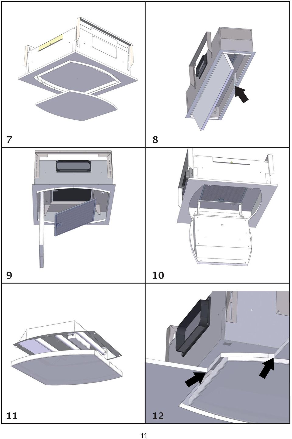
5 telepítés A készülék egy minimum 220 mm, de legfeljebb 400 mm mélységű álmennyezetbe telepíthető. Nagyobb mélység esetén egy speciális készletet kell rendelnünk, amely 400 és 580 mm mélységhez alkalmas tartókonzolokat tartalmaz. Figyelem! Amennyiben a külső motor ugyanazon rekeszbe kerül beépítésre mint az SLT955/SLT956 készülék, ellenőrizzük a külső motor befoglaló méreteit. Kiválaszthatjuk, hogy az elszívott levegő az elszívó melyik oldalán távozzon: a levegő az elszívó három oldalán, egy téglalap alakú nyíláson tud távozni. A megfelelő hely kiválasztását követően alakítsuk ki a légcsatornát. A készülékhez tartozékként jár egy 230x80 mm-es, téglalap alakú kimeneti csőgallér, melyet a kiválasztott kimeneti nyíláshoz kell csatlakoztatnunk. A nem használt kimeneti nyílásokat hagyjuk lezárva. Ezenfelül egy adapter szerelvény is jár a készülékhez, amely 150 mm átmérőjű, kör keresztmetszetű csövek csatlakoztatására szolgál (1. ábra) (amennyiben kör keresztmetszetű légcsatorna csatlakoztatását tervezzük). A tömör födémben jelöljünk határozzunk meg viszonyítási pontot, amely az elszívó pontos középpontját fogja jelölni. Jelöljük át azon pontokat, melyeket meg kell fúrni (az SLT955 esetében a 2. ábra alapján, az SLT956 esetén a 3. ábra alapján). Fúrjuk meg a lyukakat a födémben, normál 8 mm-es fúrószárral, majd illesszük be a lyukakba a tartozékként kapott dübeleket. Elegendő a 2. és 3. ábrán szereplő lyukakat megfúrni, a további belső furatokat az elszívó telepítését követően is kifúrhatjuk. A tartókeretek mélységét állítsuk a bemélyedés mélységéhez; amely legalább 220 mm, de legfeljebb 400 mm legyen. Ahogy kereteket helyükre illesztettük, rögtön húzzuk meg szorosan a tartócsavarokat. Illesszük az elszívót a rögzített keretekbe, majd a tartozékként járó csavarokkal húzzuk meg (5. ábra). Végezzük el az elektromos bekötést (6. ábra), majd csatlakoztassuk a légcsatornát a következő szakaszban leírtaknak megfelelően. Amennyiben SLT955 MODUL LIGHT vagy SLT956 MODUL LIGHT típusú készüléket telepítünk, az elektromos vezetékeket a 6. ábrán szereplő módon csatlakoztassuk. A külső motor kábelét a műanyag elektromos házból kijövő csatlakozóhoz illesszük. Az elektromos bekötés során ügyeljünk a jelölőszínek megfelelő párosítására (6. ábra). Illesszük a helyére a zsírszűrőt és zárjuk le az üveg panelt. Illesszük a helyére a gipszkarton táblát, ügyelve arra, hogy az az elszívó fém külső peremével egy síkban álljon (12. ábra). A gipszkartonba vágandó lyuk méretei a következők: SLT955: 502 mm X 502 mm két oldalon R551 mm-es lekerekítéssel. SLT956: 982 mm X 222 mm, használjuk a tartozékként kapott fúrási sablont. A 3,5 x 22-es csavarokkal rögzítsük a gipszkarton táblát az elszívóhoz, majd a megfelelő lyuk sablonnal helyezzük be ezeket. A megfelelő rögzítéshez legalább 12 csavar használata ajánlott. Amennyiben az elszívóhoz belső panel is tartozik, melyet le kívánunk fedni gipszkarton lemezzel, fa vagy egyéb anyaggal, az alábbi méretre készítsük el egy táblát: SLT955: 448x448 mm R524 lekerekítéssel a sarkokon; SLT956: 928x168 mm R524, használjuk a tartozékként kapott fúrási sablont. Rögzítsük a táblát a panelhez (7. ábra): gipszkarton esetén a tartozékként járó csavarokkal, vagy egyéb anyag esetén az ahhoz való rögzítési móddal. Vigyázat! A panel vastagságánál ne használjunk hosszabb csavarokat: maximum 3,5 x 22-es csavarokat használjunk. 5

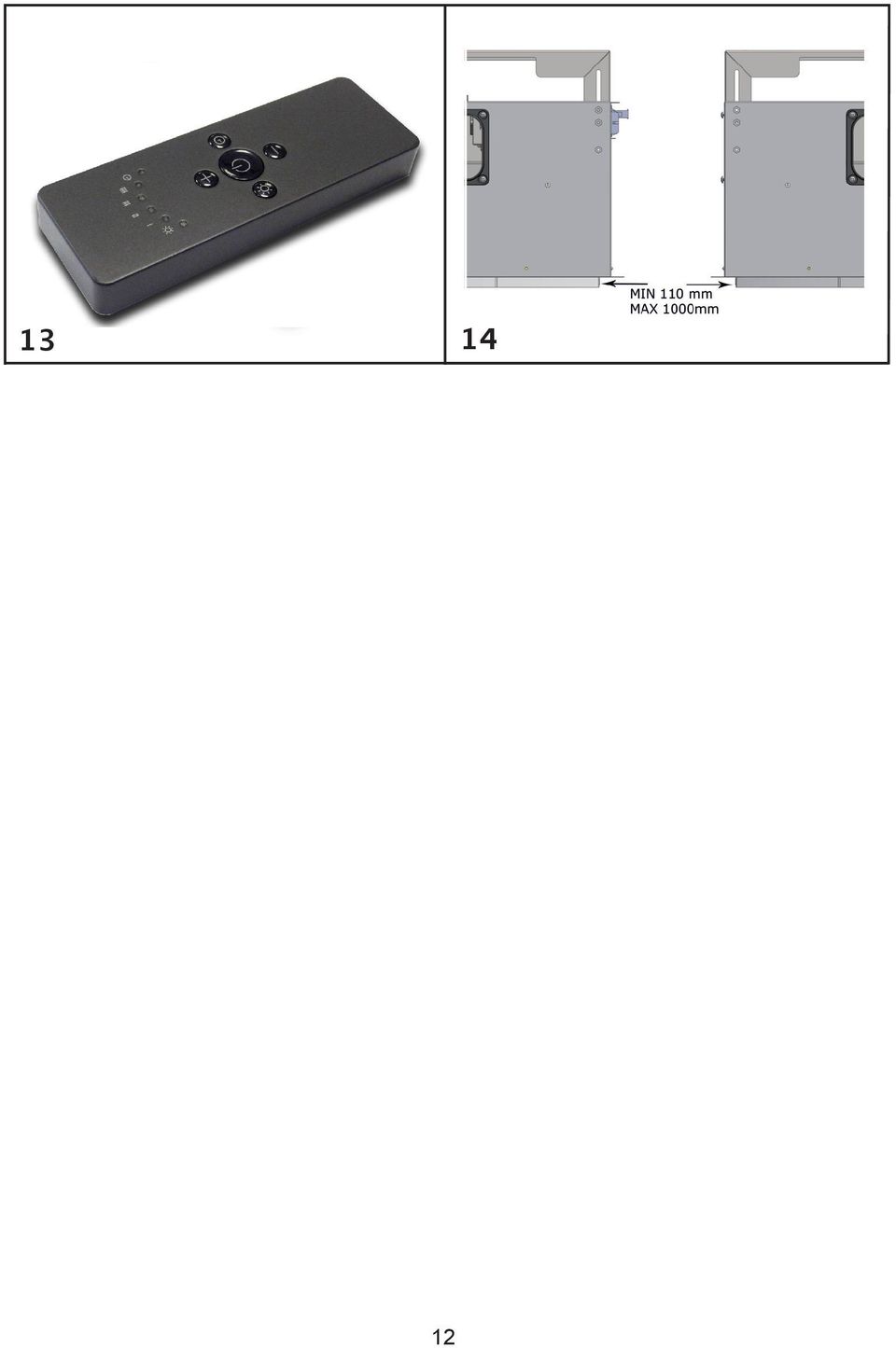
6 panel LEnyitása Nyissuk fel a panelt arról az oldalról, ahol a motor sebesség visszajelzője található (8. ábra). A lenyitás során végig tartsuk kezünket a panelnél. A panel PANEL lenyitását követően OPENING hozzáférünk a zsírszűrőhöz, majd ennek kivételét követően (használjuk Open the panel a mélyített by pulling fogantyút), it from hozzáférünk where a szénszűrőhöz the speed indicator (9. ábra). of the extraction the side motor is (Fig. 8). Accompany the panel with A your panel hands lezárásához during the egyszerűen opening. azt emeljük vízszintes Following helyzetbe the panel egészen opening, addig, you can amíg access az automatikusan the grease filter helyére and after nem its húz. removal, acting on the appropriate handle, you can reach the seat of the charcoal filter (fig. 9). To close the panel, simply bring it in horizontal position until it the automatic closing coupling occurs. csatorna rendszer Az SLT955 - SLT956 modellek esetében a fő elszívóhoz csatlakoztathatunk még egy vagy két további egységet. Ezután mint egy egységes elszívó rendszerhez csatlakoztathatunk DUCTING egyetlen belső, külső SYSTEMS vagy távoli elszívású motort. A It is több possible mint to egy install elemből a main cooker álló elszívó hood with rendszert egyetlen távvezérlőről vezérelhetjük, a further one or two MODULES SLT955 - SLT956 in a single extraction system and then connect it mivel to a single, a működtetéshez internal or external, elegendőek remote extraction a fő SLT955 motor of vagy the home. SLT956 egységek elektronikus elemei, An extraction míg a system, további formed SLT955 of more vagy than SLT956 one egységek element, is a controlled fő SLT955 by vagy a single SLT956 remote egységnetrol because megfelelően only a main fognak cooker működni. hood SLT955 or con- SLT956 has all the electronic components necessary SLT955 for the és functioning, SLT956 készülékek whilst the remaining között to- Az vábbi MODULES kombinációk SLT955 or SLT956 is kialakíthatók, are dependent mivel on egy the main fő elszívó cooker hood (SLT955 SLT955 vagy or SLT956. SLT956) megléte Other esetén combinations további can két also egység be realised is hozzáépíthető. between products SLT955 and SLT956 because only one main cooker hood (SLT955 or SLT956) is present A and gipszkarton two modules nyílásai at the maximum. között az előírt minimális távolság 110 mm, míg a megengedett A minimum distance of at least 110 mm is recommended between the openings of the plasterboard legnagyobb (Fig. 15) and a távolság maximum 1000 distance mm. of 1,000 mm. A B C 6

7 D E F G H EXTRACTION VERSIONS: Külső kivezetéses változat: A: SLT955/SLT remote motor SEM1-8* A: B: SLT955/SLT956: x module...remote SEM1-8 külső motor motor* SEM8 B: C: SLT955/SLT x x SLT955/SLT956 egység module :......remote SEM8 külső motor motor SEM8 C: D: SLT955/SLT x SLT955/SLT956 egység :... remote SEM8 motor külső SEM2-7* motor D: E: SLT955/SLT956 : x SLT955/SLT956 module... SEM2-7 remote külső motor motor* SEM7 F: SLT955/SLT x SLT955/SLT956 module... remote motor SEM7 E: SLT955/SLT x SLT955/SLT956 egység :... SEM7 külső motor F: FILTER SLT955/SLT956 VERSIONS: + 2 x SLT955/SLT956 egység :... SEM7 külső motor G: SLT955/SLT remote motor SEM1-8* + air deviator S-DF2 Szűrős H: SLT955/SLT956 változat: + 1 or 2 x SLT955/SLT956 modules. remote motor SEM8 + air deviator S-DF2 G: SLT955/SLT x SLT955/SLT956 egység : SEM1-8 külső motor + S-DF2 légterelő *High performance H: SLT955/SLT vagy 2 x SLT955/SLT956 13: SEM8 külső motor + S-DF2 légterelő *nagy teljesítményű 7

8 8 használat RC001 Távvezérlő A távvezérlő az elszívó távolról történő működtetésére szolgál. Műszaki adatok Alkáli elemek: 12 V, 23 A Üzemi frekvencia: 433,92 MHz Kombinációk száma: Max. áramfelvétel: 25 ma Üzemi hőmérséklet: -20 C ~ +55 C Méretek: 120 x 45 x 15 mm Távvezérlő használatának ismertetése A távvezérlő öt kezelőgombbal rendelkezik. Világítás BE/KI Motor BE (1. sebességf.) / Kikapcsolás Sebesség csökkentése Sebesség növelés 10 perces időkapcsoló gyári alapbeállítás A távvezérlő használatra készen, a gyári alapbeállítás szerinti jelátviteli kódra hangolva érkezik. Használat Normál kialakítás A megfelelő használathoz mind az elszívó, mind a távvezérlő egyazon jelátviteli kódra kell legyen hangolva. Amennyiben ugyanabban a helyiségben vagy egymáshoz egész közel két, rádiós vezérlésű elszívó kerül telepítésre, az egyik rendszer befolyásolhatja a másik működését azon oknál kifolyólag, hogy ugyanazzal a kóddal működik mindkét távvezérlő. Ezért szükségessé válhat az egyik vezérlőn a kód megváltoztatása. Új átviteli kód létrehozása A távvezérlő gyárilag az alapértelmezett kóddal működik. Új kód létrehozásához tegyük a következőket: Két másodperc hosszan nyomjuk le egyszerre a következő gombokat: Amikor a LED-lámpa felvillan, nyomjuk le a következő gombokat: (öt másodpercen belül). A LED-lámpa háromszor felvillan, jelezve, hogy a művelet sikeresen véget ért. VigyázAT! A művelettel véglegesen töröljük a korábbi kódokat. Új kód megtaníttatása az elszívóval A távvezérlőn új kód létrehozását követően az elszívót át kell állítanunk az új kód értelmezéséhez: nyomjuk le a főkapcsoló gombot, majd kapcsoljuk be az elektronikus vezérlő egységet. A távvezérlőn ezt követően 15 másodpercen belül nyomjuk le a 13 WORKING OPERATION MODE Standard configuration: Standard configuration requires all cooker hoods radio control - system to be provided with the same transmission code. In the event two cooker hoods radio control system are installed in the same room or nearby, each system may affect the operation of the another. Therefore, the code of one radio control system must be changed. Generating a new transmission code: The radio control system is provided with preset codes. Should new codes be required, proceed as follows: Press simultaneously buttons: for two seconds. When Leds light on, press buttons: RC001 GB RADIO CONTROL Radio control used for the remote operation of ducted cooker hoods. TECHNICAL DATA - Alkaline battery powered : 12 V mod. 23 A - Operating frequency : Mhz - Combinations : Max. consumption : 25 ma - Operating temperature : C - Dimensions : 120 x 45 x 15 mm. OPERATING DESCRIPTION The transmitter is equipped with 5 buttons for cooker hood management, as specified below: : Light ON/OFF command. : Motor ON (speed level 1) / OFF command. : Reduce speed. : Increase speed. : 10-minute timer. INITIAL OPERATING CONDITION The manufacturer supplies the radio control unit ready to be used with codes preset in the Factory. Learning the new transmission code: Once the transmission code is changed in control unit, the electronic central unit of t hood must be made to set the new code i lowing way: Press the main power-off button of the h then restore power to the electronic con Within the next 15 seconds, press the Ligh to synchronise the central unit with the Reset of the Factory configuration: To restore the Factory configuration, follow cedure described below: press simultaneo tons for 2 seconds. When Leds light on, press bu (within 5 seconds). Leds flashing 6 time! This operation deletes perman preset codes. Emergency button: In the event that the radio control does not the emergency button to switch the appl After any necessary repairs have been p reset the emergency button. The battery should be replaced every year antee the optimal range of the transmitter To replace the exhausted battery, take th lid off, remove the battery and replace it wi one, observing the correct battery polaritie Used batteries should be discarded in spe lection bins. The below product: RC001 Radio Control complies with the specifications set out R&TTE Directive 99/5/EC. Any adjustments or modifications which been expressly approved by the holder of conformity certificate may invalidate th rights relating to the operation of the devic codes. Should new codes be required, pr follows: Press simultaneously buttons: for two seconds. When Leds light on, pres (within 5 seconds). Leds flashing 3 times! This operation deletes perman preset codes. (világítás) gombot. Ezzel az elszívóval megismertettük az új kódot. Gyári alapbeállítás visszaállítása A gyári alapbeállítás visszaállításához két másodperc hosszan nyomjuk le egyszerre a következő gombokat: Amikor a LED-lámpa felvillan, nyomjuk le a következő gombokat: (öt másodpercen belül). A LED-lámpa hatszor felvillan, jelezve, hogy a művelet véget ért. VigyázAT! A művelettel véglegesen töröljük a korábbi kódokat. Vészleállítás gomb: Amennyiben a távvezérlő nem működik, a vészleállítás gombbal kapcsoljuk ki a készüléket. Javítást követően használjuk a vészleállítás gombot. WORKING Radio remote control or the remote control of cooker hoods (Fig. 13). Technical data: - Alkaline battery powered: 12V mod 23A - Operating frequency: MHz - Max. consumption: 25 ma - Operating temperature: C Working description: - To light the cooker hood on or to light it off press the button: - To increase the speed up to the fourth one press the button: - To reduce the speed up to the second one press the button: The set suction speed is shown by the LED in the perimeter extraction channel (fig. 8). Each LED colour corresponds to a different speed, as shown below: First speed WHITE Second speed LIGHT BLUE Third speed BLUE Fourth speed RED - To go from a high speed back to the first one press twice the button: - To give power to the lights or to shut them down press the button: - To set the timer up press the button: The LED on the right side will start to flash (every 5 seconds), the hood will work for 10 minutes at the selected speed and then it lights automatically off. If the client increases or reduces the speed while the timer is on, this is automatically stopped. Working mode: The first time the system is switched on, hold down the light key to set the hood with the remote control. If two cookerhoods-radiocontrol system are installed in the same room or in the immediate vicinity, each system may affect the operation of the other, due to the fact that they have the same code. Therefore it will be necessary to change the code of one of the radio controls. Warning: The battery should be replaced every year to guarantee the optimal range of the transmitter. To replace the exhausted battery, take the plastic lid off, remove the battery and replace it with a new one, observing the correct battery polarities. Used batteries should be discarded in special collection bins. The appliance has an electronic device to switch it off automatically four hours after the last operation carried out. Generating a new transmission code. The radio control is supplied with preset factory codes. If you want to create a new set of codes, proceed as follows: press and hold the UP, STOP and DOWN buttons simultaneously for 2 seconds. After the LEDS light up, press the UP and DOWN buttons within 5 seconds. The LEDS will flash 3 times to indicate that the process is completed. Warning: This procedure deletes all previously stored codes. Learning the new transmission code: After changing the transmission code on the radio control, the cooker hood electronic control unit must be made to set the new code as follows: Press the emergency button twice consecutively to cut off power to the appliance and reset it; from this moment, there are 15 seconds to press the light key so that the hood synchronises itself with the new code. OPERATION MODE Standard configuration: Standard configuration requires all cooker hoods radio control - system to be provided with the same transmission code. In the event two cooker hoods radio control system are installed in the same room or nearby, each system may affect the operation of the another. Therefore, the code of one radio control system must be changed. Generating a new transmission code: The radio control system is provided with preset codes. Should new codes be required, proceed as follows: Press simultaneously buttons: for two seconds. When Leds light on, press buttons: (within 5 seconds). Leds flashing 3 times indicate! This operation deletes permanently the preset codes. RC001 GB RADIO CONTROL Radio control used for the remote operation of duct- ed cooker hoods. TECHNICAL DATA - Alkaline battery powered : 12 V mod. 23 A - Operating frequency : Mhz - Combinations : Max. consumption : 25 ma - Operating temperature : C - Dimensions : 120 x 45 x 15 mm. OPERATING DESCRIPTION The transmitter is equipped with 5 buttons for cook- er hood management, as specified below: Light ON/OFF command. : Motor ON (speed level 1) / OFF command. : Reduce speed. : Increase speed. : 10-minute timer. NITIAL I OPERATING CONDITION The manufacturer supplies the radio control unit ready to be used with codes preset in the Factory. Learning the new transmission code: Once the transmission code is changed in the radio control unit, the electronic central unit of the cooker hood must be made to set the new code in the following way: Press the main power-off button of the hood and then restore power to the electronic control unit. Within the next 15 seconds, press the Light Button to synchronise the central unit with the code. Reset of the Factory configuration: To restore the Factory configuration, follow the procedure described below: press simultaneously buttons for 2 seconds. When Leds light on, press buttons (within 5 seconds). Leds flashing 6 times indicate! This operation deletes permanently the preset codes. Emergency button: In the event that the radio control does not work, use the emergency button to switch the appliance off. After any necessary repairs have been performed, reset the emergency button. The battery should be replaced every year to guarantee the optimal range of the transmitter. To replace the exhausted battery, take the plastic lid off, remove the battery and replace it with a new one, observing the correct battery polarities. Used batteries should be discarded in special collection bins. The below product: RC001 Radio Control complies with the specifications set out in the R&TTE Directive 99/5/EC. Any adjustments or modifications which have not been expressly approved by the holder of the legal conformity certificate may invalidate the user s rights relating to the operation of the device. Rev. 0 26/08/14 14 WORKING Radio remote control or the remote control of cooker hoods (Fig. 13). Technical data: - Alkaline battery powered: 12V mod 23A - Operating frequency: MHz - Max. consumption: 25 ma - Operating temperature: C Working description: - To light the cooker hood on or to light it off press the button: - To increase the speed up to the fourth one press the button: - To reduce the speed up to the second one press the button: The set suction speed is shown by the LED in the perimeter extraction channel (fig. 8). Each LED colour corresponds to a different speed, as shown below: First speed WHITE Second speed LIGHT BLUE Third speed BLUE Fourth speed RED - To go from a high speed back to the first one press twice the button: - To give power to the lights or to shut them down press the button: - To set the timer up press the button: The LED on the right side will start to flash (every 5 seconds), the hood will work for 10 minutes at the selected speed and then it lights automatically off. If the client increases or reduces the speed while the timer is on, this is automatically stopped. Working mode: The first time the system is switched on, hold down the light key to set the hood with the remote control. If two cookerhoods-radiocontrol system are installed in the same room or in the immediate vicinity, each system may affect the operation of the other, due to the fact that they have the same code. Therefore it will be necessary to change the code of one of the radio controls. Warning: The battery should be replaced every year to guarantee the optimal range of the transmitter. To replace the exhausted battery, take the plastic lid off, remove the battery and replace it with a new one, observing the correct battery polarities. Used batteries should be discarded in special collection bins. The appliance has an electronic device to switch it off automatically four hours after the last operation carried out. Generating a new transmission code. The radio control is supplied with preset factory codes. If you want to create a new set of codes, proceed as follows: press and hold the UP, STOP and DOWN buttons simultaneously for 2 seconds. After the LEDS light up, press the UP and DOWN buttons within 5 seconds. The LEDS will flash 3 times to indicate that the process is completed. Warning: This procedure deletes all previously stored codes. Learning the new transmission code: After changing the transmission code on the radio control, the cooker hood electronic control unit must be made to set the new code as follows: Press the emergency button twice consecutively to cut off power to the appliance and reset it; from this moment, there are 15 seconds to press the light key so that the hood synchronises itself with the new code. OPERATION MODE Standard configuration: Standard configuration requires all cooker hoods radio control - system to be provided with the same transmission code. In the event two cooker hoods radio control system are installed in the same room or nearby, each system may affect the operation of the another. Therefore, the code of one radio control system must be changed. Generating a new transmission code: The radio control system is provided with preset codes. Should new codes be required, proceed as follows: Press simultaneously buttons: for two seconds. When Leds light on, press buttons: (within 5 seconds). Leds flashing 3 times indicate! This operation deletes permanently the preset codes. RC001 GB RADIO CONTROL Radio control used for the remote operation of duct- ed cooker hoods. TECHNICAL DATA - Alkaline battery powered : 12 V mod. 23 A - Operating frequency : Mhz - Combinations : Max. consumption : 25 ma - Operating temperature : C - Dimensions : 120 x 45 x 15 mm. OPERATING DESCRIPTION The transmitter is equipped with 5 buttons for cook- er hood management, as specified below: : Light ON/OFF command. : Motor ON (speed level 1) / OFF command. : Reduce speed. : Increase speed. : 10-minute timer. INITIAL OPERATING CONDITION The manufacturer supplies the radio control unit ready to be used with codes preset in the Factory. Learning the new transmission code: Once the transmission code is changed in the radio control unit, the electronic central unit of the cooker hood must be made to set the new code in the following way: Press the main power-off button of the hood and then restore power to the electronic control unit. Within the next 15 seconds, press the Light Button to synchronise the central unit with the code. Reset of the Factory configuration: To restore the Factory configuration, follow the procedure described below: press simultaneously buttons for 2 seconds. When Leds light on, press buttons (within 5 seconds). Leds flashing 6 times indicate! This operation deletes permanently the preset codes. Emergency button: In the event that the radio control does not work, use the emergency button to switch the appliance off. After any necessary repairs have been performed, reset the emergency button. The battery should be replaced every year to guarantee the optimal range of the transmitter. To replace the exhausted battery, take the plastic lid off, remove the battery and replace it with a new one, observing the correct battery polarities. Used batteries should be discarded in special collection bins. The below product: RC001 Radio Control complies with the specifications set out in the R&TTE Directive 99/5/EC. Any adjustments or modifications which have not been expressly approved by the holder of the legal conformity certificate may invalidate the user s rights relating to the operation of the device. Rev. 0 26/08/14 l f Working mode: The first time the system is switched on, hold down the light key to set the hood with the remote control. If two cookerhoods-radiocontrol system are installed in the same room or in the immediate vicinity, each system may affect the operation of the other, due to the fact that they have the same code. Therefore it will be necessary to change the code of one of the radio controls. Warning: The battery should be replaced every year to guarantee the optimal range of the transmitter. To replace the exhausted battery, take the plastic lid off, remove the battery and replace it with a new one, observing the correct bat- Learning the new transmission code: Once the transmission code is changed in the radio control unit, the electronic central unit of the cooker hood must be made to set the new code in the following way: Press the main power-off button of the hood and then restore power to the electronic control unit. Within the next 15 seconds, press the Light Button to synchronise the central unit with the code. Reset of the Factory configuration: To restore the Factory configuration, follow the procedure described below: press simultaneously buttons for 2 seconds. When Leds light on, press buttons 14 - To set the timer up press the button: The LED on the right side will start to flash (every 5 seconds), the hood will work for 10 minutes at the selected speed and then it lights automatically off. If the client increases or reduces the speed while the timer is on, this is automatically stopped. there so the ne codes. Should new codes be required, proceed as follows: Press simultaneously buttons: for two seconds. When Leds light on, press buttons: (within 5 seconds). Leds flashing 3 times indicate! This operation deletes permanently the preset codes. An bee con righ WORKING Radio remote control or the remote control of cooker hoods (Fig. 13). Technical data: - Alkaline battery powered: 12V mod 23A - Operating frequency: MHz - Max. consumption: 25 ma - Operating temperature: C Working description: - To light the cooker hood on or to light it off press the button: - To increase the speed up to the fourth one press the button: - To reduce the speed up to the second one press the button: The set suction speed is shown by the LED in the perimeter extraction channel (fig. 8). Each LED colour corresponds to a different speed, as shown below: First speed WHITE Second speed LIGHT BLUE Third speed BLUE Fourth speed RED - To go from a high speed back to the first one press twice the button: - To give power to the lights or to shut them down press the button: - To set the timer up press the button: The LED on the right side will start to flash Working mode: The first time the system is switched on, hold down the light key to set the hood with the remote control. If two cookerhoods-radiocontrol system are installed in the same room or in the immediate vicinity, each system may affect the operation of the other, due to the fact that they have the same code. Therefore it will be necessary to change the code of one of the radio controls. Warning: The battery should be replaced every year to guarantee the optimal range of the transmitter. To replace the exhausted battery, take the plastic lid off, remove the battery and replace it with a new one, observing the correct battery polarities. Used batteries should be discarded in special collection bins. The appliance has an electronic device to switch it off automatically four hours after the last operation carried out. Generating a new transmission code. The radio control is supplied with preset factory codes. If you want to create a new set of codes, proceed as follows: press and hold the UP, STOP and DOWN buttons simultaneously for 2 seconds. After the LEDS light up, press the UP and DOWN buttons within 5 seconds. The LEDS will flash 3 times to indicate that the process is completed. Warning: This procedure deletes all previously stored codes. Learning the new transmission code: After changing the transmission code on the radio control, the cooker hood electronic control unit must be made to set the new code as follows: Press the emergency button twice consecutively to cut off power to the appliance and reset it; from this moment, there are 15 seconds to press the light key so that the hood synchronises itself with the new code. OPERATION MODE Standard configuration: Standard configuration requires all cooker hoods radio control - system to be provided with the same transmission code. In the event two cooker hoods radio control system are installed in the same room or nearby, each system may affect the operation of the another. Therefore, the code of one radio control system must be changed. Generating a new transmission code: The radio control system is provided with preset codes. Should new codes be required, proceed as follows: Press simultaneously buttons: RC001 GB RADIO CONTROL Radio control used for the remote operation of duct- ed cooker hoods. TECHNICAL DATA - Alkaline battery powered : 12 V mod. 23 A - Operating frequency : Mhz - Combinations : Max. consumption : 25 ma - Operating temperature : C - Dimensions : 120 x 45 x 15 mm. OPERATING DESCRIPTION The transmitter is equipped with 5 buttons for cook- er hood management, as specified below: : Light ON/OFF command. : Motor ON (speed level 1) / OFF command. : Reduce speed. : Increase speed. : 10-minute timer. INITIAL OPERATING CONDITION The manufacturer supplies the radio control unit ready to be used with codes preset in the Factory. Learning the new transmission code: Once the transmission code is changed in the radio control unit, the electronic central unit of the cooker hood must be made to set the new code in the following way: Press the main power-off button of the hood and then restore power to the electronic control unit. Within the next 15 seconds, press the Light Button to synchronise the central unit with the code. Reset of the Factory configuration: To restore the Factory configuration, follow the procedure described below: press simultaneously buttons for 2 seconds. When Leds light on, press buttons (within 5 seconds). Leds flashing 6 times indicate! This operation deletes permanently the preset codes. Emergency button: In the event that the radio control does not work, use the emergency button to switch the appliance off. After any necessary repairs have been performed, reset the emergency button. The battery should be replaced every year to guarantee the optimal range of the transmitter. To replace the exhausted battery, take the plastic lid off, remove the battery and replace it with a new one, observing the correct battery polarities. Used batteries should be discarded in special collection bins. The below product: RC001 Radio Control complies with the specifications set out in the R&TTE Directive 99/5/EC. Any adjustments or modifications which have not been expressly approved by the holder of the legal conformity certificate may invalidate the user s rights relating to the operation of the device. WORKING Radio remote control or the remote control of cooker hoods (Fig. 13). Technical data: - Alkaline battery powered: 12V mod 23A - Operating frequency: MHz - Max. consumption: 25 ma - Operating temperature: C Working description: - To light the cooker hood on or to light it off press the button: - To increase the speed up to the fourth one press the button: - To reduce the speed up to the second one press the button: The set suction speed is shown by the LED in the perimeter extraction channel (fig. 8). Each LED colour corresponds to a different speed, as shown below: First speed WHITE Second speed LIGHT BLUE Third speed BLUE Fourth speed RED - To go from a high speed back to the first one press twice the button: - To give power to the lights or to shut them down press the button: - To set the timer up press the button: The LED on the right side will start to flash Working mode: The first time the system is switched on, hold down the light key to set the hood with the remote control. If two cookerhoods-radiocontrol system are installed in the same room or in the immediate vicinity, each system may affect the operation of the other, due to the fact that they have the same code. Therefore it will be necessary to change the code of one of the radio controls. Warning: The battery should be replaced every year to guarantee the optimal range of the transmitter. To replace the exhausted battery, take the plastic lid off, remove the battery and replace it with a new one, observing the correct battery polarities. Used batteries should be discarded in special collection bins. The appliance has an electronic device to switch it off automatically four hours after the last operation carried out. Generating a new transmission code. The radio control is supplied with preset factory codes. If you want to create a new set of codes, proceed as follows: press and hold the UP, STOP and DOWN buttons simultaneously for 2 seconds. After the LEDS light up, press the UP and DOWN buttons within 5 seconds. The LEDS will flash 3 times to indicate that the process is completed. Warning: This procedure deletes all previously stored codes. Learning the new transmission code: After changing the transmission code on the radio control, the cooker hood electronic control unit must be made to set the new code as follows: Press the emergency button twice consecutively to cut off power to the appliance and reset it; from this moment, there are 15 seconds to press the light key so that the hood synchronises itself with OPERATION MODE Standard configuration: Standard configuration requires all cooker hoods radio control - system to be provided with the same transmission code. In the event two cooker hoods radio control system are installed in the same room or nearby, each system may affect the operation of the another. Therefore, the code of one radio control system must be changed. Generating a new transmission code: The radio control system is provided with preset codes. Should new codes be required, proceed as follows: Press simultaneously buttons: RC001 GB RADIO CONTROL Radio control used for the remote operation of duct- ed cooker hoods. TECHNICAL DATA - Alkaline battery powered : 12 V mod. 23 A - Operating frequency : Mhz - Combinations : Max. consumption : 25 ma - Operating temperature : C - Dimensions : 120 x 45 x 15 mm. OPERATING DESCRIPTION The transmitter is equipped with 5 buttons for cook- er hood management, as specified below: : Light ON/OFF command. : Motor ON (speed level 1) / OFF command. : Reduce speed. : Increase speed. : 10-minute timer. INITIAL OPERATING CONDITION The manufacturer supplies the radio control unit ready to be used with codes preset in the Factory. Learning the new transmission code: Once the transmission code is changed in the radio control unit, the electronic central unit of the cooker hood must be made to set the new code in the following way: Press the main power-off button of the hood and then restore power to the electronic control unit. Within the next 15 seconds, press the Light Button to synchronise the central unit with the code. Reset of the Factory configuration: To restore the Factory configuration, follow the procedure described below: press simultaneously buttons for 2 seconds. When Leds light on, press buttons (within 5 seconds). Leds flashing 6 times indicate! This operation deletes permanently the preset codes. Emergency button: In the event that the radio control does not work, use the emergency button to switch the appliance off. After any necessary repairs have been performed, reset the emergency button. The battery should be replaced every year to guarantee the optimal range of the transmitter. To replace the exhausted battery, take the plastic lid off, remove the battery and replace it with a new one, observing the correct battery polarities. Used batteries should be discarded in special collection bins. The below product: RC001 Radio Control complies with the specifications set out in the R&TTE Directive 99/5/EC. Any adjustments or modifications which have not been expressly approved by the holder of the legal conformity certificate may invalidate the user s rights relating to the operation of the device. VigyázAT! A távvezérlő megfelelő működése érdekében az elemet évente cseréjük: vegyük le a műanyag fedelet, vegyük ki az elemet, majd helyezzük be az újat, ügyelve a megfelelő polaritásra. A használt elemet kifejezetten erre szolgáló gyűjtőedényekben selejtezzük le. Az alábbi termék: RC001 távvezérlő megfelel a 99/5/EC R&TTE direktívában foglaltaknak. Vigyázat! A megfelelőségi tanúsítvány tulajdonosának külön engedélye nélkül végrehajtott bárminemű módosítással, átalakítással a felhasználó elveszti a készülék használatára vonatkozó jogot. 13 WORKING OPERATION MODE Standard configuration: Standard configuration requires all cooker hoods radio control - system to be provided with the same transmission code. In the event two cooker hoods radio control system are installed in the same room or nearby, each system may affect the operation of the another. Therefore, the code of one radio control system must be changed. Generating a new transmission code: The radio control system is provided with preset codes. Should new codes be required, proceed as follows: Press simultaneously buttons: for two seconds. When Leds light on, press buttons: (within 5 seconds). Leds flashing 3 times indicate RC001 GB RADIO CONTROL Radio control used for the remote operation of ducted cooker hoods. TECHNICAL DATA - Alkaline battery powered : 12 V mod. 23 A - Operating frequency : Mhz - Combinations : Max. consumption : 25 ma - Operating temperature : C - Dimensions : 120 x 45 x 15 mm. OPERATING DESCRIPTION The transmitter is equipped with 5 buttons for cooker hood management, as specified below: : Light ON/OFF command. : Motor ON (speed level 1) / OFF command. : Reduce speed. : Increase speed. : 10-minute timer. INITIAL OPERATING CONDITION The manufacturer supplies the radio control unit ready to be used with codes preset in the Factory. Learning the new transmission code: Once the transmission code is changed in the radio control unit, the electronic central unit of the cooker hood must be made to set the new code in the following way: Press the main power-off button of the hood and then restore power to the electronic control unit. Within the next 15 seconds, press the Light Button to synchronise the central unit with the code. Reset of the Factory configuration: To restore the Factory configuration, follow the procedure described below: press simultaneously buttons for 2 seconds. When Leds light on, press buttons (within 5 seconds). Leds flashing 6 times indicate! This operation deletes permanently the preset codes. Emergency button: In the event that the radio control does not work, use the emergency button to switch the appliance off. After any necessary repairs have been performed, reset the emergency button. The battery should be replaced every year to guarantee the optimal range of the transmitter. To replace the exhausted battery, take the plastic lid off, remove the battery and replace it with a new one, observing the correct battery polarities. Used batteries should be discarded in special collection bins. The below product: RC001 Radio Control complies with the specifications set out in the R&TTE Directive 99/5/EC. Any adjustments or modifications which have not been expressly approved by the holder of the legal conformity certificate may invalidate the user s rights relating to the operation of the device. for two seconds. When Leds light on, press buttons: (within 5 seconds). Leds flashing 3 times indicate! This operation deletes permanently the preset codes.

9 Időkapcsoló A termékek teljes mértékben megfelelnek az Európai Bizottság által kibocsátott és január 1-én hatályba lépett új EU65 Ökocímke és EU66 Ökotervezés irányelvekben foglaltaknak. Mindegyik modell megfelel az energiatanúsítványban foglalt követelményeknek: a készülékek egy új, időzítős elektronikával vannak ellátva, amely 650 m 3 /ó-s teljesítmény mellett korlátozza a működési időt. A belső motoros modellek esetén, ahol a maximális légszállítási teljesítmény meghaladja a 650 m 3 /ó-t, egy időzítő került beépítésre, amely 5 perces működés után a negyedik sebességfokozatról a harmadikra vált. Külső motor modellek esetén egy időzítő került beépítésre, amely 650 m 3 /ó-s teljesítmény felett korlátozza az ezen teljesítmény melletti működési időt. Olyan külső motorok esetén, ahol a légszállítási teljesítmény negyedik és harmadik fokozat mellett is meghaladja a 650 m 3 /ó-t, az alábbi időzítési vezérlési funkció került beépítésre: - Hat perc működés után az elszívási sebesség negyedik fokozatról automatikusan második fokozatra csökken; - Harmadik fokozat esetén hét perc működés után a készülék automatikusan második fokozatra vált. Készenléti állapotban a készülék áramfelvétele kevesebb mint 0,5 W. karbantartás A gondos karbantartás a készülék megfelelő és hosszú működésének záloga. A zsírszűrők különös gondoskodást igényelnek: kivételükhöz a Panel lenyitása szakaszban leírtak szerint járjunk el. A mélyített fogantyúnál fogva vegyük ki a zsírszűrőt. A tisztítást követően a zsírszűrők visszahelyezéséhez hajtsuk végre ugyanezt a műveletsort fordított sorrendben. A szénszűrő (amennyiben van) kiveteléhez először vegyük ki a zsírszűrőt: a szénszűrő közvetlenül a zsírszűrő felett helyezkedik el. A készülék tisztítása: semleges tisztítószert és langyos vizet használjunk, maró, súroló hatású tisztítószereket ne alkalmazzunk. Panel cseréje A panel cseréjéhez először a Panel lenyitása szakaszban ismertett módon nyissuk azt le; LIGHT panel esetén először áramtalanítsuk a megszakítóval a készüléket, majd a panel felett található elektromos csatlakozónál bontsuk a lámpák tápkábelének csatlakozását. Vegyük ki a panelt rögzítő két biztosítóanyát (10. ábra), majd csúsztassuk a panelt jobbra, hogy ezzel kiemeljük annak foglalatából. A visszahelyezéshez a fenti műveletsort fordított sorrendben hajtsuk végre. fénycső cseréje A kiégett fénycső cseréjéhez áramtalanítsuk a készüléket, majd a Panel lenyitása szakaszban ismertett módon nyissuk le a panelt. Vegyük ki a panel hat darab külső csavarját, majd a 11. ábrán látható módon nyissuk le a panelt. Vegyük ki a fénycsövet, majd helyezzük be az ugyanolyan típusú új fénycsövet. Helyezzük vissza a panelt és csavarjuk vissza a csavarokat. A fénycső előtét cseréjéhez ugyanígy járjunk el, mivel az előtét közvetlenül a lámpák mellett található. 9

10 AC tápf. biztosíték opcionális egységek betápja

11
12
13 Importőr: MULTIKOMPLEX BUDAPEST KFT. a páraelszívók szakértője óta H Budapest, Mansfeld Péter u. 27 (volt Bajáki Ferenc utca) tel.: +(36-1) , +(36-1) ; fax: +(36-1) GM - B 04/ /
 427 0325, +(36-1) 427-0326; fax: +(36-1)427 0327 www.")
14 INFORMAZIONI COMMERCIALI PER I CONSUMATORI COMMERCIAL INFORMATION FOR THE CONSUMER INFORMATIONS COMMERCIALES POUR LE CLIENT INFORMACIONES COMERCIALES PARA EL CLIENTE HANDELSINFORMATIONEN FÜR DEN KUNDEN COMMERCIËLE INFORMATIES VOOR DE KLANT IT EN FR ES DE NL ISTRUZIONI PER INSTALLAZIONE, USO E MANUTENZIONE INSTALLATION, USE AND MAINTENANCE INSTRUCTION INSTRUCTIONS POUR L INSTALLATION D EMPLOI ET D ENTRETIEN INSTRUCCIONES PARA LA INSTALACIÓN DE USO Y MANTENIMIENTO INSTALLATIONSANLEITUNG FÜR DIE VERWENDUNG UND WARTUNG INSTALLATIE INSTRUCTIES VOOR GEBRUIK EN ONDERHOUD SLT955 - SLT956 ENERGY LABEL INFORMAZIONI TECNICHE TECHNICAL INFORMATION INFORMATION TECHNIQUES INFORMACIONES TÉCNICAS TECHNISCHE INFORMATIONEN TECHNISCHE INFORMATIES

15 IT EN FR ES DE NL Il simbolo sul prodotto o sulla confezione indica che il prodotto non deve essere considerato come un normale rifiuto domestico, ma deve essere portato nel punto di raccolta appropriato per il riciclaggio di apparecchiature elettriche ed elettroniche. Provvedendo a smaltire questo prodotto in modo appropriato, si contribuisce a evitare potenziali conseguenze negative per l ambiente e per la salute, che potrebbero derivare da uno smaltimento inadeguato del prodotto. Per informazioni più dettagliate sul riciclaggio di questo prodotto, contattare l ufficio comunale, il servizio locale di smaltimento rifiuti o il negozio in cui è stato acquistato il prodotto. Questo elettrodomestico è marcato conformemente alla Direttiva Europea 2002/96/CE sui rifiuti da apparecchiature elettriche ed elettroniche (WEEE). The symbol on the product or on its packaging indicates that this product may not be treated as household waste. Instead it shall be handed over to the applicable collection point for the recycling of electrical and electronic equipment. By ensuring this product is disposed of correctly, you will help prevent potential negative consequences for the environment and human health, which could otherwise be caused by inappropriate waste handling of this product. For more detailed information about recycling of this product, please contact your local city office, your household waste disposal service or the shop where you purchased the product. This appliance is marked according to the European directive 2002/96/EC on waste electrical and electronic equipment (WEEE). Le symbole sur le produit ou son emballage indique que ce produit ne peut être traité comme déchet ménager. Il doit plutôt être remis au point de ramassage concerné, se chargeant du recyclage du matériel électrique et électronique. En vous assurant que ce produit est éliminé correctement, vous favorisez la prévention des conséquences négatives pour l environnement et la santé humaine qui, sinon, seraient le résultat d un traitement inappropriée des déchets de ce produit. Pour obtenir plus de détails sur le recyclage de ce produit, veuillez prendre contact avec le bureau municipal de votre région, votre service d élimination des déchets ménagers ou le magasin où vous avez acheté le produit. Cet appareil est commercialisé en accord avec la directive européenne 2002/96/CE sur les déchets del équipements électriques et électroniques (WEEE). El símbolo en el producto o en su embalaje indica que este producto no se puede tratar como desperdicios normales del hogar. Este producto se debe entregar al punto de recolección de equipos eléctricos y electrónicos para reciclaje. Al asegurarse de que este producto se deseche correctamente, usted ayudará a evitar posibles consecuencias negativas para el ambiente y la salud pública, lo cual podría ocurrir si este producto no se manipula de forma adecuada. Para obtener información más detallada sobre el reciclaje de este producto, póngase en contacto con la administración de su ciudad, con su servicio de desechos del hogar o con la tienda donde compró el producto. Este electrodoméstico está marcado conforme a la directiva Europea 2000/96/CE sobre los residuos de aparatos eléctricos y electrónicos (WEEE). Das Symbol auf dem Produkt oder seiner Verpackung weist darauf hin, dass dieses Produkt nicht als normaler Haushaltsabfall zu behandeln ist, sondern an einem Sammelpunkt für das Recycling von elektrischen und elektronischen Geräten abgegeben werden muss. Durch Ihren Beitrag zum korrekten Entsorgen dieses Produkts schützen Sie die Umwelt und die Gesundheit Ihrer Mitmenschen. Umwelt und Gesundheit werden durch falsches Entsorgen gefährdet. Weitere Informationen über das Recycling dieses Produkts erhalten Sie von Ihrem Rathaus, Ihrer Müllabfuhr oder dem Geschäft, in dem Sie das Produkt gekauft haben. Dieses Elektrohaushaltsgerät ist entsprechend der EU-Richtlinie 2002/96/CE Über Elektro-und Elektronik Altgeräte (WEEE). Het symbool op het product of op de verpakking wijst erop dat dit product niet als huishoudafval mag worden behandeld. Het moet echter naar een plaats worden gebracht waar elektrische en elektronische apparatuur wordt gerecycled. Als u ervoor zorgt dat dit product op de correcte manier wordt verwijderd, voorkomt u mogelijk voor mens en milieu negatieve gevolgen die zich zouden kunnen voordoen in geval van verkeerde afvalbehandeling. Voor meer details in verband met het recyclen van dit product, neemt u het best contact op met de gemeentelijke instanties, het bedrijf of de dienst belast met de verwijdering van huishoudafval of de winkel waar u het product hebt gekocht. Dit apparrat voldoet aan de Europese richtlijnen 2002/96/CE voor elektrische en elektronische afval (WEEE). 1

16 CONTENTS EN Warnings. Use. Installation Panel opening. Ducting systems. Working. Maintenance 9

17 S * The appliance is not intended for use by young children or infirm persons without supervision. Young children should be supervised to ensure they do not play with the appliance. * The air sucked can t be conveyed through or into a duct used to let out fumes from appliances fed by energy other than electric power (eg. centralized heating, radiators, water-heaters, etc.). * To evacuate the air outlet, please comply with the pertaining rules given by competent authorities. If the appliance is equipped with a power cord and a plug, it shall be placed in such a way that the plug can be reached easily. * The use of materials which can burst into flames (flambé) should be avoided in close proximity of the appliance. When frying, please pay particular attention to fire risk due to oil and grease. Being highly inflammable, fried oil is especially dangerous. Do not use uncovered electric grills. In order to avoid possible fire risk, all instructions for grease-filter cleaning and for removing eventual grease deposits should be strictly followed. * Two persons are needed for the installation of this product. The cooker hood, when evacuating the sucked air, could generate a negative pressure in the room- which can t exceed the limit of 0.04 mbar, in order to avoid the suck of exhausts deriving from the heat-source. Therefore the room should be provided with air-intakes to allow a constant flow of fresh air. * When performing the electrical connections on the appliance, please make sure that them current-tap is provided with earth connection and that voltage values correspond to those indicated on the label placed inside the appliance itself. * Please disconnect the appliance from power mains, before carrying out any cleaning or maintenance operation. If the appliance is not equipped with a nonseparable flexible cable and plug, or with another device ensuring omnipolar disconnection from the mains, with an opening distance between the contacts of at least 3 mm, then such disconnecting devices must be provided in the fixed installation. 10 USE The product is not equipped with the duction motor, therefore it must be coupled to a suction unit (remote motor) of the same manufacturer. INSTALLATION To install the product is necessary to make a countertop minimum depth of at least 220 mm up to a maximum of 400 mm. For greater depths it is necessary to ask the special KIT with mounting brackets for ceiling depth from 400mm to 580mm. Attention: If a remote motor is installed in the same compartment as products SLT955/SLT956, check the overall dimensions of the remote motor. You can choose the side of the hood from which to run off the sucked air; there are air outlets of rectangular shape on three sides of the hood. After choosing the best location, set up the channel, the supply provided includes an air outlet flange of rectangular shape 230x80mm to be installed on the chosen outlet. Leave closed the air exhaust holes are not used. There is also a fitting included, that allows the use of tubes with a diameter equal to 150 mm (see fig. 1), if you plan to create a circular air outlet duct. Tig bra into Pla and Per spo ets ing Ma and the DU If i SLT tric con SLT Ins tha hoo The pla - S cur - S ing Use pla the We a g

18 on c- u- and fix it with the screws supplied (see fig. 5). The tion product unit (remote is not motor) equipped of the with same the duction manufacturer. therefore it must be coupled to a suc- and Perform fix it the with holes the screws into the supplied ceiling (see in fig. corre- 5). Place the cooker hood in an established area motor, tion unit (remote motor) of the same manufacturer. Tighten Perform ets and fix strongly the definitively holes the into fastening the the product ceiling screws by in apply- corre- of the spondence of the central holes of the brack- Tighten brackets spondence strongly the fastening screws of INSTALLATION ing the remaining immediately of the central screws. after holes you of placed the brack- them USE brackets USE into and position. fix immediately definitively after the product you placed by applying Make the the remaining electrical screws. connection (see fig. 6) them into position. INSTALLATION To The install product the is product not equipped is necessary with the to duction make Place The product is not equipped with the duction and connect the cooker the air hood discharge in an established pipe following area a motor, countertop therefore minimum it must depth be coupled of at least to a suction install up unit to (remote a maximum product motor) of is 400 of necessary the mm. same For to manu- great- make and fix it with the screws supplied (see fig. 5). 220 Place and Make the cooker hood in an established area motor, therefore it must be coupled to a suction unit (remote motor) of the same manu- DUCTING connect SYSTEMS. the air discharge pipe following the instructions fix the it with electrical the given screws connection in supplied the related (see section fig. 5). 6) To mm a facturer. countertop depths it is minimum necessary depth to ask of at the least special 220 Perform the facturer. If installing instructions the an holes SLT given into 955 in the the MODUL ceiling related LIGHT in section corre- mm KIT with up to mounting a maximum brackets of 400 for mm. ceiling For greater from depths 400mm it is to necessary 580mm. to ask the special spondence ets If of the central holes of the brack- depth Perform the holes into the ceiling in corre- SLT spondence DUCTING 956 MODUL SYSTEMS. of the central LIGHT, holes connect of the the brack- electrical installing and wire fix of definitively an the SLT MODUL 955 the LIGHT MODUL product hood LIGHT by applying connectors the 956 remaining MODUL shown screws. LIGHT, in figure connect 6 SLT955 the elec- or to the or KIT with ets and fix definitively the product by applying the remaining screws. INSTALLATION mounting brackets for ceiling depth SLT from Attention: 400mm INSTALLATION If to a 580mm. remote motor is installed trical SLT956. wire of the MODUL LIGHT hood to the in the same compartment as products connectors Make the electrical shown in connection figure 6 on (see SLT955 fig. or 6) To Attention: SLT955/SLT956, install the If a product remote check is the motor necessary overall is installed to dimensions countertop the of same the remote minimum compartment motor. depth of as at products least 220 and the connect the air discharge pipe following make Make and SLT956. the electrical connection (see fig. 6) To install the product is necessary to make Install connect the plasterboard the air discharge sheet pipe making following sure a in a countertop minimum depth of at least 220 that instructions it fits perfectly given to the in the metal related edge section of the mm SLT955/SLT956, up to a maximum check of the 400 overall mm. For dimensions You depths can of the choose it remote is necessary the motor. side of ask the the hood special terminal greater Connect the DUCTING instructions the given in the related section mm up to a maximum of 400 mm. For greater depths it is necessary to ask the special The installing hood (Fig SYSTEMS. external motor s cable to the Install the 12). plasterboard sheet making sure from DUCTING If SYSTEMS. board dimensions an found SLT of the 955 in side hole MODUL the plastic to make LIGHT box that it fits perfectly to the metal edge in of the or KIT which with to mounting run off the brackets sucked for air; ceiling there are depth of air SLT If the installing an SLT 955 MODUL LIGHT or KIT with mounting brackets for ceiling depth plasterboard 956 wiring MODUL. Make are: LIGHT, sure to connect respect the the colors hood (Fig 12). electrical from You outlets can 400mm of choose rectangular to 580mm. the side shape of the on three hood sides from of SLT cables 956 MODUL LIGHT, connect the electrical connectors wire (fig.6). from 400mm to 580mm. - SLT955: wire when of 502 the perfor mm MODUL ming X 502 LIGHT the electrical mm hood with to connection The dimensions of the hole to make in two the which of the hood. to run off the sucked air; there are air plasterboard of the MODUL LIGHT hood to the curved sides shown are: R551, in figure 6 on SLT955 or Attention: outlets After choosing of rectangular If a the remote best shape location, motor on is three set installed up sides Refit the connectors SLT956. the grease shown filter in and figure close 6 on the SLT955 glass panels. - or Attention: If a remote motor is installed SLT956: SLT955: mm mm X 222 X 502 mm, mm use with the drilling template sides provided. R551, two in of channel, the hood. same the supply compartment provided includes as products an air SLT956. curved in the same compartment as products SLT955/SLT956, After outlet choosing flange of rectangular the check best the location, shape overall 230x80mm set dimensions channel, check the overall dimen- up the Install - SLT956: the 982 plasterboard mm X 222 sheet mm, use making the drilling the plasterboard sheet making sure sure SLT955/SLT956, to be of installed the remote supply on the provided motor. chosen includes outlet. an Leave air that Install sions of the remote motor. Use template the it fits 3.5 perfectly x provided. 22 screws to the supplied metal edge to fix of the outlet closed flange the air of rectangular exhaust holes shape are 230x80mm not used. hood that it fits perfectly to the metal edge of the plasterboard (Fig 12). to the cooker hood and insert You to There be can installed is choose also a on fitting the the side included, chosen of the outlet. that hood allows Leave from The hood Use (Fig 12). You can choose side of the hood from them the dimensions using 3.5 x the 22 of appropriate screws the hole supplied to hole make to template. fix in the which closed the use to the of run tubes air off exhaust with the sucked a diameter holes air; are equal there not to are used. 150 air The plasterboard dimensions of the hole to make in the which to run off the sucked air; there are air We recommend are: to at the least cooker 12 screws hood and to obtain insert outlets There mm (see is of fig. also rectangular 1), a if fitting you plan shape included, to create on three that a circular allows sides - plasterboard them are: outlets rectangular shape on three sides a good SLT955: using fixation. 502 the mm appropriate X 502 mm hole with template. two of the air the outlet use hood. of duct. tubes with a diameter equal to 150 curved - We SLT955: recommend sides 502 R551, at mm least X screws mm with to obtain two of After mm the (see choosing hood. fig. 1), the if you best plan location, to create set a circular up the - curved a sides R551, After choosing the best location, set up the In good SLT956: case fixation. the 982 hood mm is provided X 222 mm, with use an the internal drilling SLT956: 982 mm X 222 mm, use the drill- channel, air Identify outlet a the duct. reference supply provided point compared includes to an the air - channel, the supply provided includes an air panel template be covered provided. in plasterboard, wood or outlet exact centre flange of for rectangular hood installation shape 230x80mm in the solid ing In template provided. outlet flange of rectangular shape 230x80mm other case material, the hood make is provided a sheet of with the an following internal to Identify ceiling. be installed Then a reference mark on the out point the chosen area compared outlet. for the to Leave holes the Use panel to be installed on the chosen outlet. Leave dimensions: the be 3.5 covered x 22 screws in plasterboard, supplied to wood fix the or closed exact to be centre drilled, the air for at exhaust hood the points installation holes shown are in not in the figure used. solid plasterboard Use other the 3.5 x 22 screws supplied to fix the closed the air exhaust holes are not used. - SLT955: material, 448 to mm make the X cooker a 448 sheet mm hood of with the and following R524 insert on There ceiling. 2 for the is Then also item mark a SLT955 fitting out or included, the fig. area 3 for that the the allows holes item them plasterboard dimensions: to the cooker hood and insert There is also a fitting included, that allows corners, using the appropriate hole template. the to SLT956. be use drilled, of tubes at with the a points diameter shown equal in to figure 150 We them - using the appropriate hole template. the use of tubes with a diameter equal to 150 SLT955: SLT956: recommend mm at least X mm, screws with use to the R524 obtain drilling good template corners, fixation. supplied. on mm 2 for (see the fig. item 1), SLT955 if you plan or fig. to create 3 for a the circular item a We the recommend at least 12 screws to obtain mm (see fig. 1), if you plan to create a circular air SLT956. Make outlet the duct. holes in the solid ceiling, using a a - good SLT956: fixation. 928 mm X 168 mm, use the drilling Install case template the the sheet hood supplied. is to provided the panel with (fig. an 7), internal using air outlet duct. suitable 8 mm helical drill bit and insert the Identify Make plugs the provided. a holes reference in It the is point sufficient solid compared ceiling, to drill using to the a panel In case the hood is provided with an internal Identify a reference point compared to the screws be covered provided in in plasterboard, the case of wood plasterboard material, or the using sheet make the to appropriate the a sheet panel of (fig. the adhesive following 7), using for or exact suitable outer holes centre 8 mm shown for helical hood in figure installation drill bit 2 or and figure in insert the 3; solid the other panel Install be covered in plasterboard, wood or exact centre for hood installation in the solid ceiling. plugs inner holes provided. Then can mark be It drilled out is sufficient the after area installing for to the drill holes the dimensions: other material, make a sheet of the following ceiling. Then mark out the area for the holes the type screws of material provided to in be the secured. case of plasterboard to outer hood. be holes drilled, shown at the in figure points 2 shown or figure in figure 3; the - dimensions: to be drilled, at the points shown figure Caution: SLT955: or Do using 448 not mm the use X appropriate screws 448 mm longer with adhesive than R524 the for on 2 inner for holes the item can SLT955 be drilled or fig. after 3 installing for the item the - the SLT955: 448 mm X 448 mm with R524 on 2 for the item SLT955 or fig. 3 for the item panel type corners, thickness, of material maximum to be secured. 3.5 x 22. SLT956. hood. Adjust the excursion of the fixing brackets - the Caution: SLT956: corners, Do 928 not mm use X screws 168 mm, longer use the than drilling panel SLT956: template thickness, 928 supplied. mm maximum X 168 mm, 3.5 use x 22. the drill- the SLT956. according to the depth of the niche; min. - Make Adjust 220mm, the the max. holes excursion 400mm in the of solid as, the shown ceiling, fixing in brackets using Fig. 4. a ing template supplied. Make suitable according the 8 holes mm to the helical in depth the drill solid of bit the ceiling, and niche; insert using min. the a Install the sheet to the panel (fig. 7), using suitable plugs 220mm, provided. 8 max. mm 400mm helical It is drill sufficient as, bit shown and to insert drill Fig. the the Install screws the sheet provided to the in the panel case (fig. of 7), plasterboard the screws or using provided the appropriate in the case adhesive of plaster- for using Tighten plugs outer holes provided. strongly shown the It in is fastening figure sufficient 2 or screws figure to drill of 3; the brackets outer inner holes immediately shown can be in drilled figure after after you 2 or installing placed figure 3; them 12 the board type or of using material the appropriate to be secured. adhesive for into inner hood. position. holes can be drilled after installing the Caution: the type of Do material not use to screws be secured. longer than the hood. panel Caution: thickness, Do not use maximum screws 3.5 longer x 22. than the Place Adjust the the cooker excursion hood of in an the established fixing brackets area panel thickness, maximum 3.5 x 22. and Adjust according fix it the with to excursion the screws depth of supplied the of the fixing niche; (see brackets fig. min. 5). according 220mm, max. to the 400mm depth as, of shown the niche; in Fig. min. 4. Perform 220mm, the max. holes 400mm into the as, shown ceiling in Fig. correspondence of the central holes of the brack ets and fix definitively the product by apply- 12

19 PANEL OPENING DUCTING SYSTEMS Open the panel by pulling it from the side where the speed indicator of the extraction motor is (Fig. 8). Accompany the panel with your hands during the opening. Following the panel opening, you can access the grease filter and after its removal, acting on the appropriate handle, you can reach the seat of the charcoal filter (fig. 9). To close the panel, simply bring it in horizontal position until it the automatic closing coupling occurs. It is possible to install a main cooker hood with a further one or two MODULES SLT955 - SLT956 in a single extraction system and then connect it to a single, internal or external, remote extraction motor of the home. An extraction system, formed of more than one element, is controlled by a single remote control because only a main cooker hood SLT955 or SLT956 has all the electronic components necessary for the functioning, whilst the remaining MODULES SLT955 or SLT956 are dependent on the main cooker hood SLT955 or SLT956. Other combinations can also be realised between products SLT955 and SLT956 because only one main cooker hood (SLT955 or SLT956) is present and two modules at the maximum. A minimum distance of at least 110 mm is recommended between the openings of the plasterboard (Fig. 15) and a maximum distance of 1,000 mm. A B C 12

20 D E F G H EXTRACTION VERSIONS: A: SLT955/SLT remote motor SEM1-8* B: SLT955/SLT x SLT955/SLT956 module...remote motor SEM8 C: SLT955/SLT x SLT955/SLT956 module...remote motor SEM8 D: SLT955/SLT remote motor SEM2-7* E: SLT955/SLT x SLT955/SLT956 module... remote motor SEM7 F: SLT955/SLT x SLT955/SLT956 module... remote motor SEM7 FILTER VERSIONS: G: SLT955/SLT remote motor SEM1-8* + air deviator S-DF2 H: SLT955/SLT or 2 x SLT955/SLT956 modules.. remote motor SEM8 + air deviator S-DF2 *High performance 13

TYPE: FSEE. Használati útmutató. UP right. Ökocímke. Műszaki adatok. Típus: FSED-FSEB
 RMACIONES COMERCIALES PARA EL CLIENTE DELSINFORMATIONEN FÜR DEN KUNDEN MERCIËLE INFORMATIES VOOR DE KLANT E L Használati útmutató ISTRUZIONI PER L USO S-DD3 INSTRUCTIONS FOR USE S-DD3 INSTRUCTIONS POUR
TYPE: FSLA - FSLB - FSLC - FSLD I GB F E D HU
 INFORMAZIONI COMMERCIALI PER I CONSUMATORI COMMERCIAL INFORMATION FOR THE CONSUMER INFORMATIONS COMMERCIALES POUR LE CLIENT INFORMACIONES COMERCIALES PARA EL CLIENTE HANDELSINFORMATIONEN FÜR DEN KUNDEN
KN-CP50. MANUAL (p. 2) Digital compass. ANLEITUNG (s. 4) Digitaler Kompass. GEBRUIKSAANWIJZING (p. 10) Digitaal kompas
 Digital compass. ANLEITUNG (s. 4) Digitaler Kompass. GEBRUIKSAANWIJZING (p. 10) Digitaal kompas") KN-CP50 MANUAL (p. ) Digital compass ANLEITUNG (s. 4) Digitaler Kompass MODE D EMPLOI (p. 7) Boussole numérique GEBRUIKSAANWIJZING (p. 0) Digitaal kompas MANUALE (p. ) Bussola digitale MANUAL DE USO (p.
KN-CP50 MANUAL (p. ) Digital compass ANLEITUNG (s. 4) Digitaler Kompass MODE D EMPLOI (p. 7) Boussole numérique GEBRUIKSAANWIJZING (p. 0) Digitaal kompas MANUALE (p. ) Bussola digitale MANUAL DE USO (p.
Using the CW-Net in a user defined IP network
 Using the CW-Net in a user defined IP network Data transmission and device control through IP platform CW-Net Basically, CableWorld's CW-Net operates in the 10.123.13.xxx IP address range. User Defined
HAMBURG Használati útmutató Vezérlőmodul UKSM 24VDC Cikkszám: 260.033
 HABURG Használati útmutató Vezérlőmodul UKS 24VDC Cikkszám: 260.033 Brandschutz-Technik und Rauchabzug GmbH Schnackenburgallee 41d D-22525 Hamburg Germany +49 40 89 71 20-0 Fax: +49 40 89 71 20-20 Internet:
MAKING MODERN LIVING POSSIBLE. Danfoss Heating Solutions
 MAKING MODERN LIVING POSSIBLE Danfoss Danfoss Link Link HC Hidronikus HC Hydronic szabályozó Controller Szerelési Installation útmutató Guide Danfoss Heating Solutions Szerelési útmutató Tartalomjegyzék
Utasítások. Üzembe helyezés
 HASZNÁLATI ÚTMUTATÓ Üzembe helyezés Utasítások Windows XP / Vista / Windows 7 / Windows 8 rendszerben történő telepítéshez 1 Töltse le az AORUS makróalkalmazás telepítőjét az AORUS hivatalos webhelyéről.
TRENDnetVIEW Pro szoftvert. ŸGyors telepítési útmutató (1)
") TRENDnetVIEW Pro szoftvert ŸGyors telepítési útmutató (1) TRENDnetVIEW Pro/05.29.2014 Tartalomjegyzék TRENDnetVIEW Pro Management Software követelmények... 13 TRENDnetVIEW Pro Telepítése... 14 Videokamerák
TRENDnetVIEW Pro szoftvert ŸGyors telepítési útmutató (1) TRENDnetVIEW Pro/05.29.2014 Tartalomjegyzék TRENDnetVIEW Pro Management Software követelmények... 13 TRENDnetVIEW Pro Telepítése... 14 Videokamerák
Csatlakozás a BME eduroam hálózatához Setting up the BUTE eduroam network
 Csatlakozás a BME eduroam hálózatához Setting up the BUTE eduroam network Table of Contents Windows 7... 2 Windows 8... 6 Windows Phone... 11 Android... 12 iphone... 14 Linux (Debian)... 20 Sebők Márton
SL903-P SM903 SL EM903-P SL907
 RMACIONES COMERCIALES PARA EL CLIENTE DELSINFORMATIONEN FÜR DEN KUNDEN MERCIËLE INFORMATIES VOOR DE KLANT E L Használati útmutató ISTRUZIONI PER L USO S-DD3 INSTRUCTIONS FOR USE S-DD3 INSTRUCTIONS POUR
MINO V2 ÁLLVÁNY CSERÉJE V4-RE
 MINO V2 remote controlled MINO V2 ÁLLVÁNY CSERÉJE V4-RE Mino V3 circuit board replacement Mino V2-V4 csere készlet ezüst Art# 59348S, Mino V2-V4 csere készlet fehér Art# 59348W V4 áramköri lap Art# 75914
BKI13ATEX0030/1 EK-Típus Vizsgálati Tanúsítvány/ EC-Type Examination Certificate 1. kiegészítés / Amendment 1 MSZ EN 60079-31:2014
 (1) EK-TípusVizsgálati Tanúsítvány (2) A potenciálisan robbanásveszélyes környezetben történő alkalmazásra szánt berendezések, védelmi rendszerek 94/9/EK Direktíva / Equipment or Protective Systems Intended
1. Gyakorlat: Telepítés: Windows Server 2008 R2 Enterprise, Core, Windows 7
 1. Gyakorlat: Telepítés: Windows Server 2008 R2 Enterprise, Core, Windows 7 1.1. Új virtuális gép és Windows Server 2008 R2 Enterprise alap lemez létrehozása 1.2. A differenciális lemezek és a két új virtuális
English PATROL 24VDC SOROMPÓ HASZNÁLATI UTASÍTÁS
 English PATROL 24VDC SOROMPÓ HASZNÁLATI UTASÍTÁS English 3.3 Hand configuration changing As standard the system is supplied in right-hand configuration. To fit the barrier in the left-hand position, follow
Cashback 2015 Deposit Promotion teljes szabályzat
 Cashback 2015 Deposit Promotion teljes szabályzat 1. Definitions 1. Definíciók: a) Account Client s trading account or any other accounts and/or registers maintained for Számla Az ügyfél kereskedési számlája
Presenter SNP6000. Register your product and get support at HU Felhasználói kézikönyv
 Register your product and get support at www.philips.com/welcome Presenter SNP6000 HU Felhasználói kézikönyv 1 a b c d e 2 3 4 Federal Communication Commission Interference Statement This equipment has
Széchenyi István Egyetem www.sze.hu/~herno
 Oldal: 1/6 A feladat során megismerkedünk a C# és a LabVIEW összekapcsolásának egy lehetőségével, pontosabban nagyon egyszerű C#- ban írt kódból fordítunk DLL-t, amit meghívunk LabVIEW-ból. Az eljárás
Személyes adatváltoztatási formanyomtatvány- Magyarország / Personal Data Change Form - Hungary
 Személyes adatváltoztatási formanyomtatvány- Magyarország / Personal Data Change Form - Hungary KITÖLTÉSI ÚTMUTATÓ: A formanyomtatványon a munkavállaló a személyes adatainak módosítását kezdeményezheti.
Használati útmutató SLT960. ökocímke. Műszaki adatok. Típus: FSED FSEB FSEA
 Használati útmutató SLT960 ökocímke Műszaki adatok Típus: FSED FSEB FSEA A terméken vagy a csomagoláson a bal oldalon látható szimbólum jelzi, hogy a termék normál lakossági hulladékként nem selejtezhető.
ASUS GX800 lézeres játékegér
 ASUS GX800 lézeres játékegér 1 6 Felhasználói kézikönyv HUG5761 Elsö kiadás (V1) Május 2010 Copyright 2010 ASUSTeK Computer Inc. All Rights Reserved. Az ASUSTeK COMPUTER INC. ( ASUS ) előzetes írásos engedélye
EN United in diversity EN A8-0206/419. Amendment
 22.3.2019 A8-0206/419 419 Article 2 paragraph 4 point a point i (i) the identity of the road transport operator; (i) the identity of the road transport operator by means of its intra-community tax identification
T Á J É K O Z T A T Ó. A 1108INT számú nyomtatvány a http://www.nav.gov.hu webcímen a Letöltések Nyomtatványkitöltő programok fülön érhető el.
 T Á J É K O Z T A T Ó A 1108INT számú nyomtatvány a http://www.nav.gov.hu webcímen a Letöltések Nyomtatványkitöltő programok fülön érhető el. A Nyomtatványkitöltő programok fület választva a megjelenő
LIBRETTO ISTRUZIONI. Használati útmutató
 Italiano English Deutsch Français Español Português LIBRETTO ISTRUZIONI на русском языке Cod. 110030252 (CAPPE AD ISOLA) Használati útmutató INSTRUCTIONS BOOKLET BEDIENUNGSSANLEITUNG Sziget páraelszívókhoz
PIACI HIRDETMÉNY / MARKET NOTICE
 PIACI HIRDETMÉNY / MARKET NOTICE HUPX DAM Másnapi Aukció / HUPX DAM Day-Ahead Auction Iktatási szám / Notice #: Dátum / Of: 18/11/2014 HUPX-MN-DAM-2014-0023 Tárgy / Subject: Változások a HUPX másnapi piac
1.1. EGYETLEN KÉSZÜLÉK ÜZEMBE HELYEZÉSE... 124 1.2. KÉT KÉSZÜLÉK ÜZEMBE HELYEZÉSE... 124 2.1. BEKAPCSOLT/KÉSZENLÉTI ÁLLAPOT... 125
 TÁRGYMUTATÓ Fejezet 1: ÜZEMBE HELYEZÉS...124 1.1. EGYETLEN KÉSZÜLÉK ÜZEMBE HELYEZÉSE... 124 1.2. KÉT KÉSZÜLÉK ÜZEMBE HELYEZÉSE... 124 Fejezet 2: FUNKCIÓK...125 2.1. BEKAPCSOLT/KÉSZENLÉTI ÁLLAPOT... 125
Zephyr használati utasítás
 Zephyr használati utasítás fontos óvintézkedések Ez a termék háztartási használatra készült. Elektromos termékek használatánál, különösen gyermekek jelenlétében, mindig be kell tartani a következő alapvető
16F628A megszakítás kezelése
 16F628A megszakítás kezelése A 'megszakítás' azt jelenti, hogy a program normális, szekvenciális futása valamilyen külső hatás miatt átmenetileg felfüggesztődik, és a vezérlést egy külön rutin, a megszakításkezelő
használati utasítás TV-Dex
 használati utasítás TV-Dex 2 tartalom a csomag tartalma... 4 Az eszköz leírása...5 TV-Controller...7 TV-Base...8 LED.... 9 kezdetek....10 Az egységek csatlakoztatása:... 10 Amikor egynél több tv-base egységet
SL85 SL85 TC SL86 TC SL87 SL87 TC
 Használati útmutató INFORMAZIONI COMMERCIALI PER I CONSUMATORI COMMERCIAL INFORMATION FOR THE CONSUMER INFORMATIONS COMMERCIALES POUR LE CLIENT INFORMACIONES COMERCIALES PARA EL CLIENTE HANDELSINFORMATIONEN
Proxer 7 Manager szoftver felhasználói leírás
 Proxer 7 Manager szoftver felhasználói leírás A program az induláskor elkezdi keresni az eszközöket. Ha van olyan eszköz, amely virtuális billentyűzetként van beállítva, akkor azokat is kijelzi. Azokkal
ASUS Transformer Pad útmutató
 útmutató TF300TG 3G kapcsolatkezelő A SIM-kártya behelyezése 1. Egy kiegyenesített gemkapocs segítségével nyomja meg a SIMkártyatartó kilökő gombját. HUG7210 2. Vegye ki a tartót. Helyezze el a kártyát
BT HS 112 1 021 204 122
 Communication BT HS 112 1 021 204 122 www.blaupunkt.com Tartalom BT HS 112 Bluetooth headset...2 Biztonsági tudnivalók és általános információk...3 Ártalmatlanítási tájékoztatók...3 A csomag tartalma...3
(NGB_TA024_1) MÉRÉSI JEGYZŐKÖNYV
 MÉRÉSI JEGYZŐKÖNYV") Kommunikációs rendszerek programozása (NGB_TA024_1) MÉRÉSI JEGYZŐKÖNYV (5. mérés) SIP telefonközpont készítése Trixbox-szal 1 Mérés helye: Széchenyi István Egyetem, L-1/7 laboratórium, 9026 Győr, Egyetem
Kommunikációs rendszerek programozása (NGB_TA024_1) MÉRÉSI JEGYZŐKÖNYV (5. mérés) SIP telefonközpont készítése Trixbox-szal 1 Mérés helye: Széchenyi István Egyetem, L-1/7 laboratórium, 9026 Győr, Egyetem
A vitorlázás versenyszabályai a 2013-2016. évekre angol-magyar nyelvű kiadásának változási és hibajegyzéke
 A vitorlázás versenyszabályai a 2013-2016. évekre angol-magyar nyelvű kiadásának változási és hibajegyzéke A dokumentum A vitorlázás versenyszabályai a 2013-2016. évekre angol-magyar nyelvű kiadásában
Kezdőlap > Termékek > Szabályozó rendszerek > EASYLAB és TCU-LON-II szabályozó rendszer LABCONTROL > Érzékelő rendszerek > Típus DS-TRD-01
 Típus DS-TRD FOR EASYLAB FUME CUPBOARD CONTROLLERS Sash distance sensor for the variable, demand-based control of extract air flows in fume cupboards Sash distance measurement For fume cupboards with vertical
White Paper. Grounding Patch Panels
 White Paper Grounding Patch Panels Tartalom 1. Bevezető... 1 2. A földelés jelentőssége... 3 3. AC elosztó rendszer... 3 4. Földelési rendszerek... 3 4.1. Fa... 3 4.2. Háló... 5 5. Patch panel földelési
MP3-FMTRANS50. MANUAL (p. 2) CAR MP3 FM+BLUETOOTH TRANSMITTER INCL. REMOTE CONTROL. ANLEITUNG (s. 4) AUTO MP3 FM+BT TRANSMITTER INKL.
 CAR MP3 FM+BLUETOOTH TRANSMITTER INCL. REMOTE CONTROL. ANLEITUNG (s. 4) AUTO MP3 FM+BT TRANSMITTER INKL.") MP3-FMTRANS50 MANUAL (p. 2) CAR MP3 FM+BLUETOOTH TRANSMITTER INCL. REMOTE CONTROL ANLEITUNG (s. 4) AUTO MP3 FM+BT TRANSMITTER INKL. FB MODE D EMPLOI (p. 6) Transmetteur MP3, FM + Bluetooth avec télécommande
MP3-FMTRANS50 MANUAL (p. 2) CAR MP3 FM+BLUETOOTH TRANSMITTER INCL. REMOTE CONTROL ANLEITUNG (s. 4) AUTO MP3 FM+BT TRANSMITTER INKL. FB MODE D EMPLOI (p. 6) Transmetteur MP3, FM + Bluetooth avec télécommande
Személyes adatváltoztatási formanyomtatvány - Magyarország / Personal Data Change Form - Hungary
 Személyes adatváltoztatási formanyomtatvány - Magyarország / Personal Data Change Form - Hungary Kitöltési útmutató: A formanyomtatványon a munkavállaló a személyes adatainak módosítását kezdeményezheti.
REMOTE RADAR DETECTOR (connectable to GPS DETECTOR device.) BEÉPÍTHETŐ RADARDETEKTOR (GPS DETECTOR készülékhez) USER MANUAL / HASZNÁLATI ÚTMUTATÓ
 BEÉPÍTHETŐ RADARDETEKTOR (GPS DETECTOR készülékhez) USER MANUAL / HASZNÁLATI ÚTMUTATÓ") REMOTE RADAR DETECTOR (connectable to GPS DETECTOR device.) BEÉPÍTHETŐ RADARDETEKTOR (GPS DETECTOR készülékhez) USER MANUAL / HASZNÁLATI ÚTMUTATÓ 1 REMOTE RADAR DETECTOR (connectable to GPS DETECTOR device.)
REMOTE RADAR DETECTOR (connectable to GPS DETECTOR device.) BEÉPÍTHETŐ RADARDETEKTOR (GPS DETECTOR készülékhez) USER MANUAL / HASZNÁLATI ÚTMUTATÓ 1 REMOTE RADAR DETECTOR (connectable to GPS DETECTOR device.)
HASZNÁLATI ÚTMUTATÓ INOX RÚDMIXER. Modell: OHBIN-9805
 HASZNÁLATI ÚTMUTATÓ INOX RÚDMIXER Modell: OHBIN-9805 Kérjük, olvassa el figyelmesen ezt a tájékoztatót a készülék üzembehelyezése és használata előtt és őrizze meg ezt az információt jövőbeli használatra.
ENROLLMENT FORM / BEIRATKOZÁSI ADATLAP
 ENROLLMENT FORM / BEIRATKOZÁSI ADATLAP CHILD S DATA / GYERMEK ADATAI PLEASE FILL IN THIS INFORMATION WITH DATA BASED ON OFFICIAL DOCUMENTS / KÉRJÜK, TÖLTSE KI A HIVATALOS DOKUMENTUMOKBAN SZEREPLŐ ADATOK
CONTROL AUTÓRIASZTÓ RENDSZER
 CONTROL AUTÓRIASZTÓ RENDSZER FELHASZNÁLÓI KÉZIKÖNYV TARTALOM: HASZNÁLATI UTASÍTÁS AZ ÜZEMMÓDOK LEÍRÁSA ÉS JELLEMZŐI VEZETÉKEZÉSI UTMUTATÓ BEÉPÍTÉSI ÚTMUTATÓ www.metroman.hu 1. A RIASZTÓ ÉLESÍTÉSE (1) A
(Asking for permission) (-hatok/-hetek?; Szabad ni? Lehet ni?) Az engedélykérés kifejezésére a következő segédigéket használhatjuk: vagy vagy vagy
 (-hatok/-hetek?; Szabad ni? Lehet ni?) Az engedélykérés kifejezésére a következő segédigéket használhatjuk: vagy vagy vagy") (Asking for permission) (-hatok/-hetek?; Szabad ni? Lehet ni?) SEGÉDIGÉKKEL Az engedélykérés kifejezésére a következő segédigéket használhatjuk: vagy vagy vagy A fenti felsorolásban a magabiztosság/félénkség
(Asking for permission) (-hatok/-hetek?; Szabad ni? Lehet ni?) SEGÉDIGÉKKEL Az engedélykérés kifejezésére a következő segédigéket használhatjuk: vagy vagy vagy A fenti felsorolásban a magabiztosság/félénkség
Küchenradio Keukenradio Radio de cuisine Radio para cocina Radio da cucina Kitchen radio Radio kuchenne Konyhai rádió Кухонне радіо Радио для кухни
 D NL F E I GB PL H UA RUS Küchenradio Keukenradio Radio de cuisine Radio para cocina Radio da cucina Kitchen radio Radio kuchenne Konyhai rádió Кухонне радіо Радио для кухни Bedienungsanleitung/Garantie
Construction of a cube given with its centre and a sideline
 Transformation of a plane of projection Construction of a cube given with its centre and a sideline Exercise. Given the center O and a sideline e of a cube, where e is a vertical line. Construct the projections
Lexington Public Schools 146 Maple Street Lexington, Massachusetts 02420
 146 Maple Street Lexington, Massachusetts 02420 Surplus Printing Equipment For Sale Key Dates/Times: Item Date Time Location Release of Bid 10/23/2014 11:00 a.m. http://lps.lexingtonma.org (under Quick
4-42 ELECTRONICS WX210 - WX240
 4-42 ELECTRONICS WX210 - WX240 PCS 40000499-en Fig. 8 WX210 - WX240 ELECTRONICS 4-43 PCS COMPONENTS 40000471-en Load-limit regulator Legend Fig. 1 Fig. 2 1 Power supply 2 PWM1 output, proportional valve
USER MANUAL Guest user
 USER MANUAL Guest user 1 Welcome in Kutatótér (Researchroom) Top menu 1. Click on it and the left side menu will pop up 2. With the slider you can make left side menu visible 3. Font side: enlarging font
Ültetési és öntözési javaslatok. Planting and watering instructions
 Ültetési és öntözési javaslatok Planting and watering instructions 1 Önöntöző-rendszer Sub-irrigation 2 Kedves növénykedvelő A LECHUZA önöntöző rendszerrel növényeink természetüknél fogva gyönyörű virágokat
Contact us Toll free (800) fax (800)
 fax (800)") Table of Contents Thank you for purchasing our product, your business is greatly appreciated. If you have any questions, comments, or concerns with the product you received please contact the factory.
Table of Contents Thank you for purchasing our product, your business is greatly appreciated. If you have any questions, comments, or concerns with the product you received please contact the factory.
BT Drive Free 411 1 021 104 411
 Communication BT Drive Free 411 1 021 104 411 www.blaupunkt.com Tartalom BT Drive Free 411...3 Bluetooth technológia...3 Biztonsági tudnivalók és általános információk...4 Ártalmatlanítási tájékoztatók...5
Gitárerősítő. Használati utasítás
 Gitárerősítő Használati utasítás Óvintézkedések Olvassa el figyelmesen az utasításokat! Tartsa be ezeket az utasításokat! Vegyen figyelembe minden figyelmeztetést! Kövessen minden utasítást! Ne használja
Felhasználói kézikönyv
 LÉGKONDICIONÁLÓ BERENDEZÉS (OSZTOTT TÍPUS) Felhasználói kézikönyv Beltéri egység Modell neve: Oldalfali típus RAV-SM307KRTP-E RAV-SM407KRTP-E Kereskedelmi használatra Felhasználói kézikönyv Magyar Translated
ISTRUZIONI PER L USO INSTRUCTIONS FOR USE MODE D EMPLOI BEDIENUNGSANLEITUNG FOLLETO DE INSTRUCCIONES???????????????????????????? HASZNÁLATI ÚTMUTATÓ
 ISTRUZIONI PER L USO INSTRUCTIONS FOR USE MODE D EMPLOI BEDIENUNGSANLEITUNG FOLLETO DE INSTRUCCIONES???????????????????????????? HASZNÁLATI ÚTMUTATÓ SPECCHIO BIFOCALE BIFOCAL MIRROR MIROIR BIFOCAL DREHBAR
sorozat CD4 Katalógus füzetek
 sorozat CD4 Katalógus füzetek Bosch Rexroth AG Pneumatics sorozat CD4 3/2 szelep, sorozat CD4 Qn = 900 l/min, Menetes csatlakozás G1/8, egyoldali működtetésű, elektromos csatlakozóhoz, B-forma 3 5/2 szelep,
Formula Sound árlista
 MIXERS FF-6000; FF6000P Formula Sound 160 6 channel dual format DJ mixer with removable fader panel. (Supplied with linear faders) Formula Sound 160P As above but with PRO X crossfade fitted. Formula Sound
Honeywell. HCW 82 Alapjel állító / HCF 82 Helyiség hőmérséklet érzékelő HCW 82/HCF 82 Telepítés és működés
 Honeywell HCW 82 Alapjel állító / HCF 82 Helyiség hőmérséklet érzékelő HCW 82/HCF 82 Telepítés és működés Tartalomjegyzék 1.1. Alkalmazás... 5 1.2. HCW 82/HCF 82 különbségek... 6 Külső betáplálás csatlakoztatásának
EL-ES03HQ. English Deutsch Français Nederlands Italiano Español Magyar Suomi Svenska Česky Română Ελληνικά. MANUAL (p. 2) TV SMART POWER SAVER
 TV SMART POWER SAVER") MANUAL (p. 2) TV SMART POWER SAVER MODE D EMPLOI (p. 8) Economiseur d énergie intelligent pour TV MANUALE (p. 14) RISPARMIATORE DI ENERGIA PER TV HASZNÁLATI ÚTMUTATÓ (o. 20.) INTELLIGENS TV ENERGIAMEGTAKARÍTÓ
MANUAL (p. 2) TV SMART POWER SAVER MODE D EMPLOI (p. 8) Economiseur d énergie intelligent pour TV MANUALE (p. 14) RISPARMIATORE DI ENERGIA PER TV HASZNÁLATI ÚTMUTATÓ (o. 20.) INTELLIGENS TV ENERGIAMEGTAKARÍTÓ
Bemutatás. Elrendezés. Leírás. Műszaki adatok. Funkciók
 Bemutatás Leírás A legújabb fejlesztésű STIM DSCR univerzális vevőegység a DSC egyirányú vezeték nélküli eszközeinek a jelzéseit fogadja és azokat 5 darab szabadon konfigurálható relével bármilyen központra
User Manual. Central locking system PNI 288
 User Manual Central locking system PNI 288 1 OPERATING INSTRUCTIONS 1. Lock doors: press the key on the remote, warning lights will blink once and the doors will be locked. 2. Unlock doors: press the key
A katalógusban szereplő adatok változásának jogát fenntartjuk. 2015. 02-es kiadás
 RUGÓKATALÓGUS A Biotek Kft. több mint 20 év tudásával és tapasztalatával valamint kiváló minőségű rögzítéstechnikai és gépépítő elemek nagy választékával kínál megoldásokat termékek tervezéséhez és gyártásához.
ControlBox WiFi. Electrolux légkondicionáló berendezésekhez
 ControlBox WiFi Electrolux légkondicionáló berendezésekhez Biztonsági figyelmeztetések TELEPÍTÉS FIGYELEM! Meghibásodás lehetősége, hő és füst jelenség! Mielőtt megkezdené a készülék telepítését és használatát,
AS-i illesztő-tápegység Pick-to Light rendszerekhez. Kábel keresztmetszet
 AS-I ILLESZTŐ-TÁPEGYSÉG PTL RENDSZEREKHEZ KVL-AGW01 FŐBB PARAMÉTEREK AS-i vezérlők illesztését végzi a KVL COMP által gyártott PTL rendszerekhez. 3 A terhelhetőségű AS-i tápegység. 5 A terhelhetőségű tápegység
MELLÉKLET / ANNEX. EU MEGFELELŐSÉGI NYILATKOZAT-hoz for EU DECLARATION OF CONFORMITY
 TRACON BUDAPEST KFT. TRACON BUDAPEST LTD. 2120 DUNAKESZI, PALLAG U. 23. TEL.: (27) 540-000, FAX: (27) 540-005 WWW.TRACON.HU EU MEGFELELŐSÉGI NYILATKOZAT, a 79/1997. (XII. 31.) IKIM számú és a 374/2012.
ÏÄÇÃÉÅÓÿ ÓÕÍÁÑÌÏËÏÃÇÓÇÓÿ ÊÁÉÿ ÑÇÓÇÓ
 D GB F NL I E P RU GR PL HU CZ MONTAGE- UND GEBRAUCHSANWEISUNG INSTRUCTION ON MOUNTING AND USE PRESCRIPTIONS DE MONTAGE ET MODE D EMPLOI MONTAGEVOORSCHRIFTEN EN GEBRUIKSAANWIIZING ISTRUZIONI DI MONTAGGIO
Az Ön kézikönyve LG CS09AF http://hu.yourpdfguides.com/dref/3911641
 Elolvashatja az ajánlásokat a felhasználói kézikönyv, a műszaki vezető, illetve a telepítési útmutató. Megtalálja a választ minden kérdésre az a felhasználói kézikönyv (információk, leírások, biztonsági
A modern e-learning lehetőségei a tűzoltók oktatásának fejlesztésében. Dicse Jenő üzletfejlesztési igazgató
 A modern e-learning lehetőségei a tűzoltók oktatásának fejlesztésében Dicse Jenő üzletfejlesztési igazgató How to apply modern e-learning to improve the training of firefighters Jenő Dicse Director of
3. MINTAFELADATSOR KÖZÉPSZINT. Az írásbeli vizsga időtartama: 30 perc. III. Hallott szöveg értése
 Oktatáskutató és Fejlesztő Intézet TÁMOP-3.1.1-11/1-2012-0001 XXI. századi közoktatás (fejlesztés, koordináció) II. szakasz ANGOL NYELV 3. MINTAFELADATSOR KÖZÉPSZINT Az írásbeli vizsga időtartama: 30 perc
www.global-export-import.eu
 JÓTÁLLÁSI JEGY Az alábbi típusú és gyártási számú VIDEÓ KAPUTELEFON hibamentes működéséért a. 49/2003. (VII. 30.) GKM rendelet alapján a vonatkozó jogszabályok előírásai szerint az eladás napjától számított
KEZELÉSI ÚTMUTATÓ. Kezelési útmutató vezeték nélküli kézi egységhez. Magyar. OM-GS02-1011(1)-Daikin Part No.: R08019037090A MODE TURBO TIMER CANCEL
-Daikin Part No.: R08019037090A MODE TURBO TIMER CANCEL") KEZELÉSI ÚTMUTATÓ Kezelési útmutató vezeték nélküli kézi egységhez Magyar SWING FAN TURBO MODE QUIET SLEEP ON TIMER OFF CLOCK OM-GS02-1011(1)-Daikin Part No.: R08019037090A GS02 távirányító bemutatása
KEZELÉSI ÚTMUTATÓ Kezelési útmutató vezeték nélküli kézi egységhez Magyar SWING FAN TURBO MODE QUIET SLEEP ON TIMER OFF CLOCK OM-GS02-1011(1)-Daikin Part No.: R08019037090A GS02 távirányító bemutatása
INSTRUCTIONS FOR USE S-DD3 INSTRUCTIONS FOR USE S-DD2 INSTRUCTIONS POUR L EMPLOI S-DD3 INSTRUCTIONS POUR L EMPLOI S-DD2
 INFORMAZIONI COMMERCIALI PER I CONSUMATORI PER I CONSUMATORI COMMERCIAL INFORMATION INFORMATION THE FOR CONSUMER THE CONSUMER INFORMATIONS COMMERCIALES COMMERCIALES POUR LE POUR CLIENT LE CLIENT INFORMACIONES
EN United in diversity EN A8-0206/445. Amendment
 21.3.2019 A8-0206/445 445 Title Proposal for a DIRECTIVE OF THE EUROPEAN PARLIAMENT AND OF THE COUNCIL amending Directive 2006/22/EC as regards enforcement requirements and laying down specific rules with
INSTRUCTION OF USE HASZNÁLATI UTASÍTÁS MANUALE D'USO
 INSTRUCTION OF USE HASZNÁLATI UTASÍTÁS MANUALE D'USO 105095101 105095104 105095101 105095104 Tisztelt Vásárló! Köszönjük, hogy az indukciós főzőlapunkat választotta. Annak érdekében, hogy a lehető legjobban
REX OPERÁTORÚ AUTOMATA TOLÓAJTÓK FELÉLESZTÉSI, ÜZEMBE HELYEZÉSI, BESZABÁLYOZÁSI UTASÍTÁSA
 REX OPERÁTORÚ AUTOMATA TOLÓAJTÓK FELÉLESZTÉSI, ÜZEMBE HELYEZÉSI, BESZABÁLYOZÁSI UTASÍTÁSA Változat: 04/2002 Dátum: Összeállította: 2002 március Dvorák László - 2 - - 3 - - 4 - - 5 - - 6 - - 7 - ÁLTALÁNOS
Használati és beszerelési útmutató főzőlaphoz
 Használati és beszerelési útmutató főzőlaphoz Kedves Vásárlónk! Köszönjük, hogy termékünket választotta. A készülék gondos tervezés után jött létre, gyártása kizárólag kiváló minőségű anyagok felhasználásával
2 Helyezze be a CD-ROM-ot a CD-ROM meghajtóba.
 Termékismertető A: Tápfeszültség-/linkjelző LED (Link: LED bekapcsolva/villog) B: USB.0 aljzat C: Védősapka Telepítés Kapcsolja be a számítógépet. Bekapcsolás Az alábbi telepítési lépések Windows XP operációs
E1 - E1A E1BOX vezérlő panel 230 V~ egymotoros automatikákhoz, beépített rádióval
 E1 - E1A E1BOX vezérlő panel 230 V~ egymotoros automatikákhoz, beépített rádióval Szerelési útmutató Verzió: 09/2013 Dátum: 2013 szeptember Készítette: Kovács Attila -2- -3- - 4 - ÁLTALÁNOS BIZTONSÁGI
sorozat 740 Katalógus füzetek
 sorozat 740 Katalógus füzetek Bosch Rexroth AG Pneumatics sorozat 740 5/2 mágnesszelep, sorozat 740 Qn = 700-950 l/min, menetes csatlakozás, egyoldali működtetésű, elektromos csatlakozóhoz, ISO 4400 (Aforma),
THS710A, THS720A, THS730A & THS720P TekScope Reference
 THS710A, THS720A, THS730A & THS720P TekScope Reference 070-9741-01 Getting Started 1 Connect probes or leads. 2 Choose SCOPE 3 or METER mode. Press AUTORANGE. Copyright Tektronix, Inc. Printed in U.S.A.
NYOMÁSOS ÖNTÉS KÖZBEN ÉBREDŐ NYOMÁSVISZONYOK MÉRÉTECHNOLÓGIAI TERVEZÉSE DEVELOPMENT OF CAVITY PRESSURE MEASUREMENT FOR HIGH PRESURE DIE CASTING
 Anyagmérnöki Tudományok, 39/1 (2016) pp. 82 86. NYOMÁSOS ÖNTÉS KÖZBEN ÉBREDŐ NYOMÁSVISZONYOK MÉRÉTECHNOLÓGIAI TERVEZÉSE DEVELOPMENT OF CAVITY PRESSURE MEASUREMENT FOR HIGH PRESURE DIE CASTING LEDNICZKY
Külvilági kapcsolat. UPS séma ábra, kétsoros LCD DISPLAY, 8db nyomógomb. A B C D E F G H
 Külvilági kapcsolat. UPS séma ábra, kétsoros LCD DISPLAY, 8db nyomógomb. 3 KISEGITŐ hálózat INPUT MAINS hálózat FOGYASZTÓ LED 1 4 HIBA DISPLAY FUNKCIÓ nyomógombok LED INFORMÁCIÓ tartalom. A B C D E F G
TELJESÍTMÉNY NYILATKOZAT 0832-CPD-1651
 E-mail: info@fulleon.co.uk Web: www.cooperfulleon.co m TELJESÍTMÉNY NYILATKOZAT 0832-CPD-1651 Termék azonosító kód: ROLP/SV és ROLP/SV/WP Típus, adagszám vagy gyári szám, illetve bármilyen más elem, amely
CHANSON Miracle vízionizátor
 Life - Health - Happiness CHANSON Miracle vízionizátor GRANDION > Haználat elõtt, kérjük alaposan olvassa el az útmutatót! > Az útmutatóben említett,és a paneleken megjelenített ph érték területenként
DWL-G520 AirPlus Xtreme G 2,4GHz Vezeték nélküli PCI Adapter
 Ez a termék a következő operációs rendszereket támogatja: Windows XP, Windows 2000, Windows Me, Windows 98SE DWL-G520 AirPlus Xtreme G 2,4GHz Vezeték nélküli PCI Adapter Előfeltételek Legalább az alábbiakkal
MAKING MODERN LIVING POSSIBLE
 MAKING MODERN LIVING POSSIBLE Link CC Central - Központi Controller vezérlő Installation Szerelési útmutató Guide DANFOSS HEATING SOLUTIONS Link CC - Bevezetés Tartalomjegyzék Bevezetés...3 Szerelés...4
Kanadai DOC közlemény... 2. Fontos biztonsági utasítások... 3. 1. fejezet Üzembehelyezés... 4. A monitor kicsomagolása... 4
 Tartalom Elõszó... 2 FCC közlemény... 2 Kanadai DOC közlemény... 2 Fontos biztonsági utasítások... 3 1. fejezet Üzembehelyezés... 4 A monitor kicsomagolása... 4 Az LCD monitor és a talp összeillesztése...
Használati útmutató. Figyelem. Egészsége megőrzése érdekében a gépen való edzés megkezdése előtt kérje orvosa tanácsát.
 Használati útmutató Figyelem Egészsége megőrzése érdekében a gépen való edzés megkezdése előtt kérje orvosa tanácsát. Ha szédülést, émelygést észlel, azonnal hagyja abba a gépen való edzést. A gép helytelen
Tavaszi Sporttábor / Spring Sports Camp. 2016. május 27 29. (péntek vasárnap) 27 29 May 2016 (Friday Sunday)
 27 29 May 2016 (Friday Sunday)") Tavaszi Sporttábor / Spring Sports Camp 2016. május 27 29. (péntek vasárnap) 27 29 May 2016 (Friday Sunday) SZÁLLÁS / ACCOMODDATION on a Hotel Gellért*** szálloda 2 ágyas szobáiban, vagy 2x2 ágyas hostel
Tavaszi Sporttábor / Spring Sports Camp 2016. május 27 29. (péntek vasárnap) 27 29 May 2016 (Friday Sunday) SZÁLLÁS / ACCOMODDATION on a Hotel Gellért*** szálloda 2 ágyas szobáiban, vagy 2x2 ágyas hostel
STUDENT LOGBOOK. 1 week general practice course for the 6 th year medical students SEMMELWEIS EGYETEM. Name of the student:
 STUDENT LOGBOOK 1 week general practice course for the 6 th year medical students Name of the student: Dates of the practice course: Name of the tutor: Address of the family practice: Tel: Please read
1.oldal Budapest, Alsóerdősor u. 32 Tel.: / Mobil: / web:
 D and T Hungary Kft - Midea Hibakódok Hibakód (x = sötét, o = világít. * = villog) Defr. Timer Auto Oper. 1074 Budapest, Alsóerdősor u. 32 Tel.: +36-79/950-844 Mobil: +36-70/421-6940 web: www.dthungary.hu
On The Number Of Slim Semimodular Lattices
 On The Number Of Slim Semimodular Lattices Gábor Czédli, Tamás Dékány, László Ozsvárt, Nóra Szakács, Balázs Udvari Bolyai Institute, University of Szeged Conference on Universal Algebra and Lattice Theory
Road construction works
 Road construction works Info Version 2 Url http://com.mercell.com/permalink/45294693.aspx External tender id 246818-2014 Tender type Tender Document type Additional information Procurement procedure Open
LED alkalmazások. Schanda János
 LED alkalmazások Schanda János Élettartam LED-es fényforrás Színes LED lámpák Kis és nagyfeszültségre készült LED lámpák Világító dióda alkalmazása a közlekedéstechnikában Közlekedési jelzőtábla LEDes
Hometronic Manager HCM 200 HCM 200D. Telepítés és konfiguráció
 Hometronic Manager HCM 200 HCM 200D Telepítés és konfiguráció Tartalomjegyzék Tartalomjegyzék Információk a telepítési útmutatóról 2 A csomag tartalma 2 Betáplálás 3 Kábel típusok 3 Tápfeszültség 4 Bekötési
LIBRETTO ISTRUZIONI. Használati útmutató INSTRUCTIONS BOOKLET BEDIENUNGSSANLEITUNG LIVRET D INSTRUCTIONS INSTRUKCJE OBSŁUGI
 Cod. 110030291 (CIELO / AURA) LIBRETTO ISTRUZIONI Használati útmutató INSTRUCTIONS BOOKLET BEDIENUNGSSANLEITUNG LIVRET D INSTRUCTIONS INSTRUKCJE OBSŁUGI Ed. 2014 Italiano English Deutsch Français Español
Informatikai alkalmazásfejlesztő alkalmazásfejlesztő 54 481 02 0010 54 02 Információrendszer-elemző és - Informatikai alkalmazásfejlesztő
 A 10/2007 (II. 27.) SzMM rendelettel módosított 1/2006 (II. 17.) OM rendelet Országos Képzési Jegyzékről és az Országos Képzési Jegyzékbe történő felvétel és törlés eljárási rendjéről alapján. Szakképesítés,
KELER KSZF Zrt. bankgarancia-befogadási kondíciói. Hatályos: 2014. július 8.
 KELER KSZF Zrt. bankgarancia-befogadási kondíciói Hatályos: 2014. július 8. A KELER KSZF a nem-pénzügyi klíringtagjaitól, és az energiapiaci alklíringtagjaitól a KELER KSZF Általános Üzletszabályzata szerinti
Comfort típusú kezelő egység
 Comfort típusú kezelő egység Felhasználói kézikönyv Kezelő egység Tartalom Oldal Rövidítések / Jelentések Rövidítések / jelentések... 2 Nyomógombok azonosítása... 3 Képernyő jelzések... 4 Gyors indítás...
Get started Bevezetés Introducere
 Get started Bevezetés Introducere Get started Bevezetés Introducere 1 Use the supplied power adapter to connect the charging station to a power outlet. Place Eve Flare on the charging station to commence
quick installation guide
 quick installation guide The image is for reference only. ArIeS e1 2 in 1 GAMING COMBO English Thank you for purchasing the KWG ARIES E1 COMBO. The KWG ARIES E1 gaming keyboard has a comfortable design