IAN FLUX-CORED WIRE WELDER PFDS 33 A1. FLUX-CORED WIRE WELDER Translation of the original instructions TÖLTŐHUZALOS HEGESZTŐKÉSZÜLÉK
|
|
|
- Zsófia Takácsné
- 6 évvel ezelőtt
- Látták:
Átírás

1 FLUX-CORED WIRE WELDER FLUX-CORED WIRE WELDER Translation of the original instructions TÖLTŐHUZALOS HEGESZTŐKÉSZÜLÉK Az originál használati utasítás fordítása VARILNI APARAT NA POLNJENO ŽICO Prevod originalnega navodila za uporabo ZVÁRAČKA Preklad originálneho návodu na obsluhu SVÁŘEČKA NA PLNĚNOU DRÁTO- VOU ELEKTRODU Překlad originálního provozního návodu FÜLLDRAHT-SCHWEISSGERÄT Originalbetriebsanleitung IAN
2 Before reading, unfold both pages containing illustrations and familiarise yourself with all functions of the device. Olvasás előtt kattintson az ábrákat tartalmazó mindkét oldalra és végezetül ismerje meg a készülék mindegyik funkcióját. Pred branjem obe strani s slikami odprite navzven in se nato seznanite z vsemi funkcijami naprave. Před čtením si odklopte obě dvě strany s obrázky a potom se seznamte se všemi funkcemi přístroje. Pred čítaním si odklopte obidve strany s obrázkami a potom sa oboznámte so všetkými funkciami prístroja. Klappen Sie vor dem Lesen die beiden Seiten mit den Abbildungen aus und machen Sie sich anschließend mit allen Funktionen des Gerätes vertraut. GB Translation of the original instructions Page 1 HU Az originál használati utasítás fordítása Oldal 17 SI Prevod originalnega navodila za uporabo Stran 33 CZ Překlad originálního provozního návodu Strana 49 SK Preklad originálneho návodu na obsluhu Strana 65 DE / AT / CH Originalbetriebsanleitung Seite 81
3 A B
4 C D E F
5 Contents Introduction...2 Intended use...2 Residual risk....2 Features...2 Package contents....2 Technical details...3 Rating plate and explanation of symbols...3 Safety...4 Basic safety instructions....4 Special safety instructions...5 Complementary safety instructions...5 Potential hazards...6 Risk of injury due to electric shock....6 Confined spaces and hot rooms...6 Accident risks due to poor air supply in confined spaces...6 Protective clothing...6 Protection against radiation and burns...7 Risk of burns due to flying sparks...7 Risk of accidents due to spattering slag....7 Risk of fire due to flying sparks...7 Risk of explosion...7 EMC appliance classification....7 Unpacking and checking the package contents...8 Assembly...8 Fitting the welding mask...8 Filling with flux-cored wire...8 Operation Switching the appliance on and off Setting the welding current...11 Adjusting the wire feed...11 Overload protection...11 Welding mask Welding Weld types Forehand welding...12 Backhand welding Welded joints...12 Butt welds...12 Flat butt welds Welds on an outer edge...12 Welds on an inner edge...13 Overlap welds Cleaning and care...13 Wire feed...13 Cable assembly Welder Troubleshooting Disposal...15 Kompernass Handels GmbH warranty Service...15 Importer...15 Translation of the original Conformity Declaration 16 GB 1
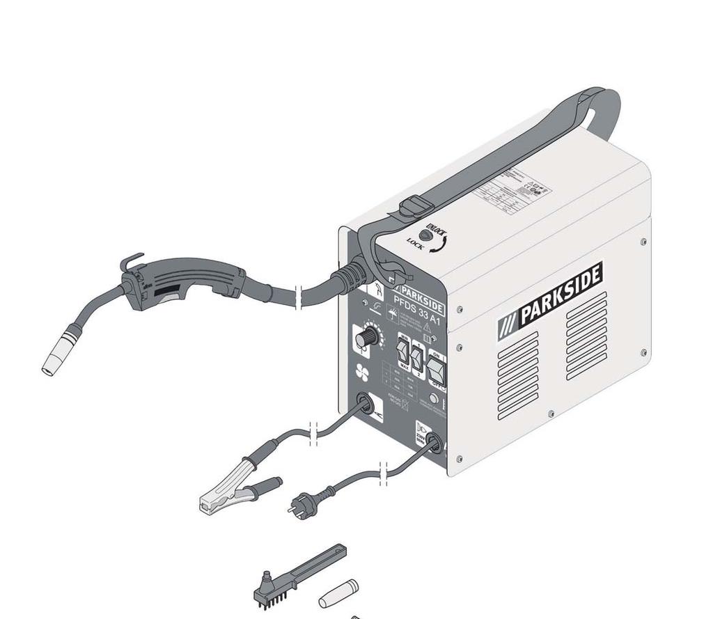
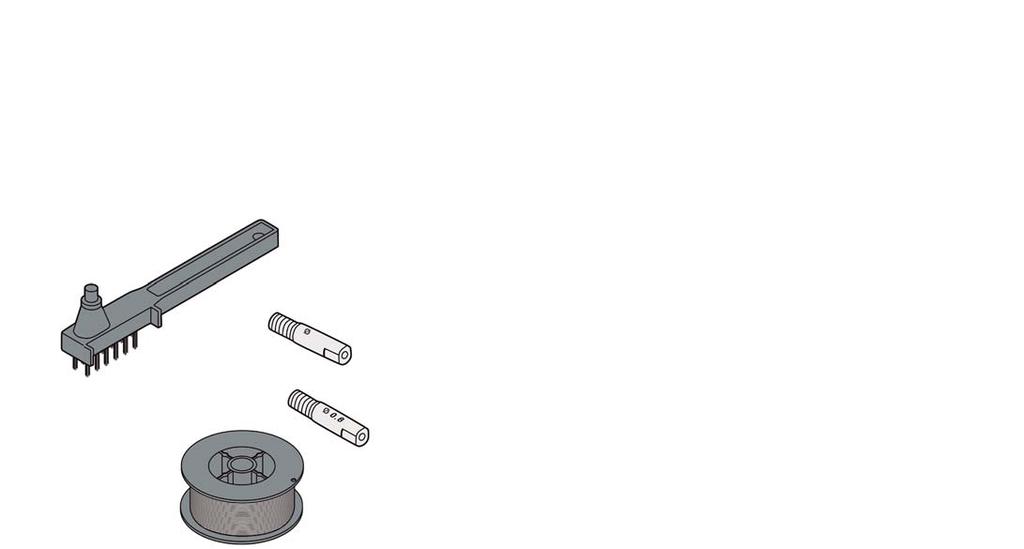
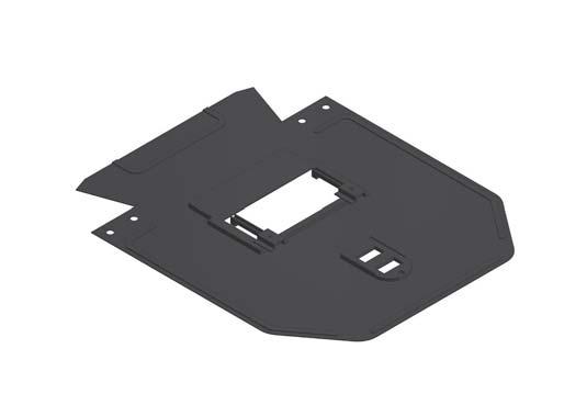
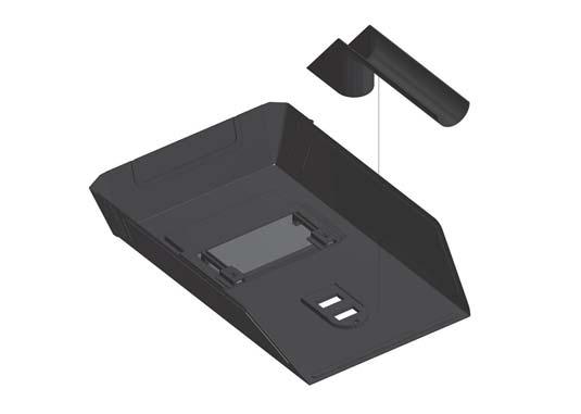
6 FLUX-CORED WIRE WELDER Introduction Congratulations on the purchase of your new appliance. You have selected a high-quality product. The operating instructions are part of this product. They contain important information about safety, usage and disposal. Before using the product, please familiarise yourself with all operating and safety instructions. Use the product only as described and for the range of applications specified. Please also pass these operating instructions on to any future owner. Intended use The appliance is suitable for self-shielded flux-core welding using an appropriate wire. No additional gas is required. The protective gas is contained in powdered form in the wire itself, is thus fed directly into the arc and means that the appliance is not susceptible to wind and can be used outside. Only the filler wire designed for this appliance may be used. Proper use also involves compliance with the safety instructions as well as the assembly instruction and the operating notes in the operating instructions. Comply exactly with the applicable accident prevention regulations. The appliance may not be used: in rooms with insufficient ventilation, in damp or wet environments, in explosive atmospheres, for the purpose of thawing pipes, in the vicinity of people with heart pacemakers and in the vicinity of flammable materials. Use this appliance only as described in this instruction manual. All other uses are deemed to be improper and may result in property damage or even in personal injury. The manufacturer is not liable for damages caused by improper or incorrect use. Residual risk Even if you operate this appliance properly, there will still be residual risks. The following risks can occur in the context of the design and construction of this flux-core welder: Features Cover wire feed unit Carrying strap Catch Mains plug Earth cable with earth clamp Cable assembly with direct connection Torch button Torch Steel sleeve Setting wheel for wire feed MIN/MAX switch for welding current 1/2 switch for welding current Main switch ON/OFF (incl. power indicator) Overload protection control lamp Torch nozzle (1.0 mm) Torch nozzle (0.8 mm) Flux-core wire spool (wire roll) Ø 0.9 mm/510 g Chipping hammer with steel brush Welding mask after assembly, consisting of: Protective plate Protective glass catch Mounting clip Dark welding lens Handle Package contents 1 flux-cored wire welder 1 steel sleeve (pre-assembled) 3 weld nozzles ( 1 x 1.0 mm pre-assembled; 1 x 0.8 mm; 1 x 1.0 mm) 1 chipping hammer with steel brush 1 flux-core wire Ø 0.9 mm/510 g 1 welding mask 1 carrying strap 1 set of operating instructions Eye injuries from flashes, Touching hot parts of the appliance or the workpiece (burns), In the case of insufficient protection, risk of accidents and burns due to flying sparks or slag, Harmful emissions of smoke and gases in the event of poor ventilation or insufficient extraction in closed rooms. Reduce the residual risks by using the appliance carefully and in accordance with all the instructions. 2 GB
7 Technical details Model: Voltage U 1 : Welding current I 2 : No-load voltage U 0 : Protection rating: Insulation class: Weight: Welding wire: Welding wire: Welding current: flux-cored wire welder 230 V ~ / 50 Hz (alternating current) 48 A/90 A 27.5 V IP 21S H 12.7 kg Ø 0.7/0.8/0.9/1.0 mm approx. 450 g Material thickness mm: with Ø 0.7 / 0.8 mm welding wire, welding current 48 A 60 A Material thickness mm: with Ø 0.8/0.9/1.0 mm welding wire, welding current 70 A 90 A Duty cycle X: 10% at 90 A welding current 60% at 48 A welding current Rating plate and explanation of symbols S/N: EN :2012 EN :2014/A1:2015 Class A 48 A / 16 V 90 A / 18.5 V ~ 50 Hz X 10 % 60 % U 0 Ø mm Single-phase transformer Nominal no-load voltage Permissible flux-core wire diameter Symbol for self-shielded flux-core welder I Rated value of the welding current 2 X Duty cycle in % U Standardised working voltage 2 1 ~ 50 Hz Mwains supply, number of phases alternating current symbol and rated value of the frequency U Rated value of the mains voltage 1 Max. rated value of the mains current I 1 max. I 1 eff IP21S Protection class H Insulation class 12.7 kg Weight of the appliance Effective value of the max. mains current (A) Follow the safety regulations Read the operating instructions Do not store or use the appliance in wet environment or in rain Symbol for welding power sources that are suitable for welding in environments with increased electrical risks. Nominal value of the required mains fuse: 16 A U 0 = 27.5 V I 2 90 A 48 A U V 16 V 1 ~ 50 Hz U 1 = 230 V I 1max = 13 A I 1eff = 4.8 A IP21S 12.7 kg GB 3
8 Wear ear protection! Wear protective goggles! Wear a dust mask! Wear protective gloves! Use the welding mask! Wear protective clothing! Wear protective shoes! Caution! Read instruction manual! Electric shock from welding electrode can kill! Breathing welding fumes can be hazardous to your health! Welding sparks can cause explosion or fire! Arc rays can burn eyes and injure skin! Electromagnetic field can cause pacemaker malfunction! Explanation of symbols The following symbols and signal words are used in these instructions, on the flux-core welder or on the packaging. HAZARD!This signal word indicates a hazard with a high degree of risk that will result in death or serious injury if not prevented. WARNING!This signal word indicates a hazard with a medium level of risk which could lead to death or serious injury if not prevented. CAUTION!This signal word indicates a hazard with a low level of risk which could result in a minor or moderate injury if not prevented. NOTE!This signal word warns of possible damage to property or gives useful additional information on assembly or operation. Safety Basic safety instructions WARNING! RISK OF ELECTROCUTION! Dangers for children and persons with limited physical, sensory or mental capabilities (for example, partially handicapped people or older people with limitations to their physical or mental abilities) or lack of experience and knowledge (for example, older children). The flux-core welder may only be used by adults. Children should be supervised to ensure they do not play with the fluxcore welder. Keep children away from the packaging materials and small components. Swallowing can lead to a risk of suffocation. Ensure that the appliance is suitably maintained. Maintenance and/or repairs may only be performed by qualified persons. In addition to the notices in these operating instructions, all general safety and accident prevention legislation must also be complied with. Always pay attention to what you are doing and always be alert. Do not work with the flux-core welder if you are distracted or under the influence of drugs, alcohol or medication. Just one moment of inattention while operating this appliance may result in an accident and serious personal injuries. Check the appliance for any possible defects before use. If the appliance exhibits any faults, it must not be used under any circumstances. Ensure that the welding lead, nozzle, the torch and earth connections are all in perfect condition. Wear on the insulation and the live parts can cause dangerous situations and reduce the quality of the welding work. Use this appliance only as described in this instruction manual. Using this appliance can lead to wear on certain parts. Therefore, check the appliance regularly for any possible damage or defects. For your own safety, use only the additional equipment and accessories specified in the operating instructions or recommended by the manufacturer. When setting up the appliance, ensure that it is placed on a stable and safe working surface. On heavily used supply networks and power circuits, welding work can lead to problems for other users. If in doubt, consult your electricity provider. Comply with all national guidelines and laws when welding. This applies, in particular, to accident prevention regulations. The flux-core welder may only be used on a stable and level surface. The flux-core welder is constructed so that it can be tilted up to a maximum of 10 from the plane before tipping over. Secure the flux-core welder against tipping if working on an inclined plane. To avoid damage to the appliance, always transport the appliance in an upright position. 4 GB
9 Special safety instructions WARNING! RISK OF ELECTROCUTION! Incorrect electrical installation, excessive mains voltage or incorrect handling can lead to an electric shock. Any electrical shock can be fatal. Do not connect the flux-core welder unless the mains voltage from the socket outlet corresponds to the requirement given on the type plate. Connect the flux-core welder only to an easily accessible socket, so that it can be quickly disconnected from the mains in the event of an accident. Do not operate the flux-core welder if it has any visible damage or the mains cable or plug are defective. The mains connection cable used is a high-quality line that must not be damaged. While working, ensure that it does not come into contact with any hot objects. If the connecting lead is damaged it must be replaced by a specific connecting lead that is available from the manufacturer or its customer service. The main connecting lead may only be replaced by the manufacturer or its customer service or a similarly qualified person. Do not open the housing except as described in these instructions. Have all repairs carried out by qualified specialists. Contact a specialist workshop. Unauthorised repairs, improper connection or incorrect operation will invalidate any liability or guarantee claims. Never insert any pointed and/or metallic objects into the interior of the appliance. Repairs may only be made using parts that correspond to the original appliance specifications. This flux-core welder contains electrical and mechanical parts that are vital as protection against sources of danger. Protect the flux-core welder from damp and use it only in dry, interior rooms. Never immerse the flux-core welder, the power cable or the plug in water or other liquids. Never touch the flux-core welder or the plug with wet hands. Avoid all direct contact with the welding current circuit. The no-load voltage between the flow nozzle and the earth clamp can be dangerous. Do not pull on the mains cable to remove the plug from the socket; always pull on the plug itself. Avoid any tensile load on the mains cable. Unplug the appliance before setting it up at a different location. Keep the flux-core welder, mains plug and power cable away from open flames and hot surfaces. Do not kink the mains cable. Protect all cables from oil, sharp edges and high temperatures. If you are not using the flux-core welder, cleaning or calibrating it or if there is a malfunction, switch off the flux-core welder and pull the plug out of the power socket. WARNING! RISK OF INJURY! Improper handling can lead to severe injuries! Position the power cable so that it does not present a tripping hazard. The light radiation emitted by the electric arc can cause damage to the eyes. Protect your eyes using suitable protective glasses (DIN EN 166, DIN EN 169/protection level 10) that you can attach to the supplied welding mask. The light radiation emitted by the electric arc can cause burns to the skin. Use gloves and dry protective clothing that is free of oil and grease to protect the skin from exposure to the ultraviolet radiation of the electric arc. The welded workpiece starts to glow and remains very hot for quite a long time. Make sure that it has cooled down before touching it. Arc welding can cause vapours to be released that may be hazardous to health. Ensure that there is no one within a radius of 15 m of the electric arc who is not wearing protective clothing and eye protection. Protect yourself and any bystanders from the possible hazardous effects of the electric arc! WARNING! RISK OF FIRE! Improper handling can lead to fires or explosions. Arc welding causes sparks, melted metal parts and smoke. Therefore ensure that you remove all flammable substances and/or materials from the working area. The welded workpiece starts to glow and remains very hot for quite a long time. It can thus come into contact with flammable materials and cause a fire. Do not weld receptacles, containers or pipes that have been used for flammable liquids or gases. WARNING! ELECTROMAGNETIC FIELDS! The flux-core welder and the electric arc can generate electrical or electromagnetic fields that can cause electronic systems and appliances to malfunction. These include IT systems, telecommunications systems, electronically controlled appliances and machines. Mains and signal lines can be interrupted. Pacemakers may also be affected. Observe the maintenance instructions. Unwind the earth cable and the cable assembly completely. Coiled cables can enhance electromagnetic fields. Provide sufficient shielding for appliances or machines sensitive to radiation. If you wear a pacemaker, consult your doctor before welding. CAUTION! Improper handling can lead to overheating of the flux-core welder and property damage. The flux-core welder may not be restricted or placed directly against the wall during its functional life to ensure that enough air can always be taken up through the ventilation slit. Make sure that there is always adequate ventilation. Complementary safety instructions Risk of electric shock: Electric shock from welding electrode can kill. Do not weld in the rain or snow. Wear dry insulating gloves. Do not touch electrode with bare hands. Do not wear wet or damaged gloves. Protect yourself from electric shock by insulating yourself from workpiece. Do not open the equipment enclosure. Risk induced by welding fumes: Breathing welding fumes can be hazardous to your health. Keep your head out of the fumes. Use equipment in an open area. Use ventilating fan to remove fumes. Risk induced by welding sparks: Welding sparks can cause explosion or fire. Keep flammables away from welding. Do not weld near flammables. Welding sparks can cause fires. Have a fire extinguisher nearby and have a watchperson ready to use it. Do not weld on drums or any closed containers. Risk induced by the arc: Arc rays can burn eyes and injure skin. Wear hat and safety glasses. Use ear protection and button shirt collar. Use welding helmet with correct shade of filter. Wear complete body protection. Risk induced by electromagnetic fields: Welding current produces electromagnetic field. Do not use with medical implants. Never coil welding cables around your body. Route the welding cables together. The safety instructions for engine driven power sources shall also include: GB 5
10 Potential hazards There are a number of potential hazards that can occur during arc welding. It is therefore particularly important for the welder to comply with the following rules to avoid endangering himself or others and prevent injuries or damage to the appliance. Do not use this flux-core welder on a surface that is inclined by more than 10. Work on the voltage side, e.g. on cables, plugs, sockets, etc., may only be carried out by qualified specialists. This applies especially to the fitting of intermediary cables. In the event of an accident, disconnect immediately from the welding power source. If electrical contact voltages occur, switch off the appliance immediately and have it checked by a qualified specialist. Always ensure good electrical contacts on the welding current side. Always wear insulating gloves on both hands during welding work. These protect the user from electric shock (no-load voltage of the welding current circuit), harmful radiation (heat and UV radiation) as well as from incandescent metal and splashes of slag. Wear sturdy insulating shoes (should also be waterproof). Loafers are not suitable as falling incandescent metal droplets can cause burns. Wear suitable clothing, no synthetic fibres. Do not look into the electric arc without eye protection; always use the welding mask with the prescribed protective glass as per DIN. In addition to the light and heat radiation, which can dazzle and/or cause burns, the electric arc also emits UV radiation. If not properly protected, this invisible ultraviolet radiation can cause a very painful conjunctivitis that is not apparent until several hours later. In addition, this UV radiation can cause sunburn-like effects on unprotected parts of the body. Any persons in the vicinity of the electric arc or helpers must be appraised of the dangers and be equipped with the necessary protective equipment. If necessary, put up protective walls. No welding work may be carried out on containers that have been used for storing gases, fuels, mineral oils or similar even if they have been empty for a long time as possible residues may present a risk of explosion. Special regulations apply in rooms where there is a risk of fire or explosion. Welded joints that are subject to heavy stress loads and are required to comply with safety requirements may only be carried out by trained and qualified welders. Examples of this are: pressure vessels, running rails, tow bars, etc. Risk of injury due to electric shock When there is no electric arc, there is a nominal no-load voltage of U 0 between the earth clamp and the flow nozzle. This voltage can be potentially fatal if the welder touches the flow nozzle, torch nozzle, welding wire or the workpiece with his/her bare hands. It is important to bear in mind that the protective conductor in electrical systems or appliances can be damaged by negligence by the welding current: e.g. the earth clamp is placed on the welder housing which is connected to the protective conductor of the electrical system. The welding work is carried out on a machine with a protective conductor connection. It is also possible to weld the machine without attaching the earth clamp to it. In this case, the welding current flows from the earth clamp via the protective conductor to the machine. The high welding current can cause the protective conductor to melt. The supply to the mains socket must be secured as per regulations (VDE 0100). In accordance with these regulations, only fuses or circuit breakers with a corresponding wire cross section may be used (16 amp circuit breaker). A too high fuse amperage can cause cable fires or building fire damage. Confined spaces and hot rooms When working in confined spaces or hot rooms, use insulated underlays, filler layers and gauntlets made of leather or a different non-conductive material to insulate your body against the floor, walls, conductive appliance parts and similar. When using welding transformers to weld in environments with increased electrical risks, e.g. in confined rooms with electrically conductive walls (boilers, pipes, etc.), in hot rooms (sweating through the work clothes), the output voltage of the flux-core welder in no-load operation may not be higher than 48 V~ (effective value). Due to its output voltage in no-load operation, the appliance may be used in this case. Accident risks due to poor air supply in confined spaces Considerable quantities of smoke and gases are produced during welding. Ensure that there is a suitable opening for the extraction of smoke and gases. Never feed oxygen into the room. This increases the risk of fire. Protective clothing While working, the welder must protect all body parts from radiation and against burns by means of clothing and the welding mask. Wear gauntlets made of a suitable material (leather) on both hands. They must be in perfect condition. To protect your clothes from flying sparks and burns, wear a suitable apron. If the type of work requires it, e.g. overhead welding, wear a protective suit and, if necessary, also the corresponding headgear. The clothing worn and all accessories must comply with the guideline Personal protective equipment (89/686/EEC). 6 GB
11 Protection against radiation and burns Warn of the danger to the eyes by hanging up a sign saying Caution, do not look into the flames!. Work areas are to be shielded so as to protect people in the vicinity. Keep unauthorised persons away from the welding work. Do not set up fixed welding locations in the immediate vicinity of light-coloured or glossy walls. Windows should be blocked off to at least head height to prevent the escape or reflection of radiation, e.g. by painting with a suitable paint. Risk of burns due to flying sparks The spraying welding sparks can cause painful burns. Therefore, observe the following guidelines: Always wear a leather apron. Use leather gloves. For overhead welding, wear suitable headgear. Ensure that your trouser cuffs fall over your shoes. Wear sturdy and insulated shoes. Risk of accidents due to spattering slag When it sets, the slag is hard and brittle. Afterwards, it can be chipped off using the chipping hammer sharp-edged particles may fly up that could seriously injure your eyes. Therefore protect your eyes by wearing suitable protective goggles when removing slag. Risk of fire due to flying sparks If molten or incandescent metal and slag particles fall onto flammable substances, these can ignite and cause a fire. Therefore, remove all flammable objects from the working area before commencing welding work. Keep a suitable fire extinguisher at hand. Pay particularly close attention to the following materials. Paper Rags Textiles Wood and wood fibres Rubber Plastic Petrol Oils Tar-like substances Paints and solvent Risk of explosion Both the welding function and the superheated weld joint itself can cause explosions. Therefore, do not use the appliance in a potentially explosive environment containing combustible liquids, gases or paint mist. Please also note: When the flux-core welder is in operation, do not lay the torch on the flux-core welder itself or any other electrical appliance. Before finishing the welding work, do not touch the flow nozzle or any other metal object with which the flow nozzle is in contact. Disconnect the appliance from the power immediately after completing your welding work. Ensure that no cable is wrapped around any body part. Make sure that you are not within the welding current circuit. The welding torch and earth must always be on the same side. EMC appliance classification As per the standard IEC , this appliance is a welding unit with class A electromagnetic compatibility. Thus it complies with the corresponding requirements for industrial and domestic use. In residential areas, it may be connected to the low voltage electricity supply. Even the flux-core welder complies with the emission limits of the standard, arc welding appliances can nevertheless cause interference to sensitive systems and appliances. The user is responsible for any interference caused by the electric arc during welding and must take appropriate preventive measures. The user must pay close attention to the following: Power, control, signal and telecommunication lines Computers and microprocessor-controlled appliances TVs, radios and other playback appliances Electronic and electrical safety appliances People with pacemakers or hearing aids Measurement and calibration systems The electromagnetic immunity of other systems in the vicinity The time of the day at which the welding work is to be carried out. To prevent possible interference radiation, we recommend: Fitting a mains filter to the mains connection or shielding it with a metal pipe Maintaining the flux-core welder regularly and keeping it in good condition Weld cables should be as short as possible, completely unwound and running as close to parallel with the floor as possible An equipotential bonding should be provided The workpieces should be properly earthed Any appliances susceptible to interference radiation should moved out of the welding area, if possible, or shielded. GB 7
12 Unpacking and checking the package contents 1.) Remove all components from the packaging and check whether the flux-core welder or the individual components show any signs of damage. If this is the case, do not use the flux-core welder. Contact the manufacturer via the service address provided on the warranty card. 2.) Remove all protective films and other transport packaging. 3.) Check that the delivery is complete. Assembly Fitting the welding mask Filling with flux-cored wire WARNING! To avoid the danger of electric shock, injury or damage: NOTE Before maintenance or pre-work preparation activity, always disconnect the mains plug from the mains power socket. Depending on the application, different types of flux-core wires will be required. This appliance can use wires with a diameter from mm. The feed roller, torch nozzle and wire diameter must always match. The appliance is designed for wire rolls of up to a maximum of 450 kg. Fold the side parts of the mask inwards. Press the integrated clips into the corresponding holes so that they click into each other (see fig. D). Open the cover of the wire feed unit by turning the catch (see arrow marking) to the position UNLOCK (see fig. 1). Lay the dark welding lens into the mask with the writing at the top (see fig. E). The writing on the dark welding lens must now be visible from the front side of the welding mask. Push the handle from the inside into the corresponding recess on mask, until it clicks into place (see fig. F). Fig. 1 Unlock the roller unit by turning the roller mount A 90 anticlockwise (see fig. 2). Pull the roller unit from the shaft (see fig. 2). Fig. 2 NOTE Make sure that the end of the wire does not come loose and cause the roll to roll out on its own. The end of the wire may not be released until during assembly. 8 GB
13 Unpack the wire roll completely so that it can be unrolled unimpeded. Do not release the wire end yet (see fig. 3). Replace the feed roll holder F and screw it tight. Place the wire roll onto the shaft. Make sure that the roll unwinds on the same side as the wire feed guide C (see fig. 3). Put the roll mount A back on and lock it by pressing and turning it clockwise 90 (see fig. 3). Fig. 6 Remove the torch nozzle by turning it to the right (see fig. 7). Unscrew the flow nozzle (see fig. 7). Route the cable assembly away from the welder as straight as possible (laying on the floor). Fig. 3 Undo the adjustment screw D and swing it upwards (see fig. 4). Fig. 4 Push the press roller unit E to the side (see fig. 5). Fig. 7 Pull the wire end from the edge of the spool (see fig. 8). Trim the wire end with a wire cutter or a diagonal cutter to remove any damaged/bent wire (see see fig. 8). NOTE THE WIRE MUST BE HOLD ON TENSION ALL THE TIME, TO AVOID A RELEASING AND ROLL OUT! We recommend that you always carry out work with the help of a second person. Fig. 5 Undo the feed roll holder F by turning it anticlockwise and pulling it upwards and off (see fig. 6). Check the upper side of the feed roll G to see if it is the correct wire size. If required, the feed roll must be turned over or exchanged. The supplied welding wire (Ø 0.9 mm) must be used in the feed roll G with the next biggest specified wire thicknesses of Ø 1.0 mm. The wire must be positioned in the upper groove! Fig. 8 GB 9
14 Push the flux-core wire through the wire feed guide C (see fig. 9). As soon as the wire juts 1 2 cm out of the torch neck M, release the torch button (see fig. 12). Fig 9 Guide the wire along the feed roll G and then push it into the cable assembly opening I (see fig. 10). Fig. 12 Switch off the welder. Screw the flow nozzle back on. Make sure that the flow nozzle matches the diameter of the welding wire being used (see fig. 13). With the supplied welding wire (Ø 0.9 mm) the flow nozzle must be used with the next largest diameter of 1.0 mm. Fig. 10 Swivel the press roller unit E in the direction of the feed roll G (See fig. 11). Hook the adjustment screw D into place (see fig. 11). Set the adjustment screw so that the welding wire sits firmly between the press roller and the feed roll G in the upper guide without being pinched (see fig. 11). Fig. 13 Push the torch nozzle back onto the torch neck M with a turn to the right (see fig. 14). Fig. 11 Switch on the welder using the main switch. Press the torch button. Now the wire feed system pushes the welding wire through the cable assembly and the torch. Fig. 14 WARNING! To avoid the danger of electric shock, injury or damage: Before maintenance or pre-work preparation activity, always disconnect the mains plug from the mains power socket. 10 GB
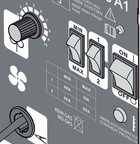
15 Operation Switching the appliance on and off Switch the welder on and off using the main switch. If you do not intend to use the welder for an extended period, remove the plug from the power socket. This is the only way to completely de-energise the appliance. Setting the welding current Use the switches welding current. on the front of the welder to set the required If, for example, the MIN switch und the switch 1 are set to the up position, the welding current is 48 A and the duty cycle is at 60%. If the MAX switch und the switch 2 are set to the down position, the welding current is 90 A and the duty cycle is at 10%. The required welding current is dependent on the diameter of the welding wire being used, the material thickness and the desired penetration depth. MIN MAX 1 48 A 70 A 2 60 A 90 A Adjusting the wire feed To achieve a consistent weld result, you can make fine adjustments to the wire feed using the setting wheel for the wire feed. We recommend using a setting in the middle range to start with and then increasing or reducing the speed as required. The required welding flow is dependent on the diameter of the welding wire being used, the material thickness and the desired penetration depth as well as the bridging distance between the two pieces being welded. Overload protection The welder is protected against overheating by an automatic protection appliance (thermostat with automatic restart) metal clad. The protection appliance interrupts the power supply in the event of an overload and the yellow overload protection control lamp lights up. If the protection appliance activates, allow the appliance to cool down (approx. 15 minutes). As soon as the yellow overload protection control lamp goes off, the appliance is again ready for use. Welding mask WARNING! HEALTH HAZARD! If you do not use the welding mask, the harmful UV radiation and the heat coming from the electric arc can damage your eyes. Always use the welding mask when you weld. Welding WARNING! RISK OF BURNS! Welded, hot workpieces are very hot so that you could burn yourself. Always use pliers to move welded, hot workpieces. After you have connected the welder to the power, proceed as follows: Connect the earth cable to the workpiece that is to be welded using the earth clamp. Ensure that there is a good electrical connection. The workpiece should be free of rust and paint where the weld is to made. Select the desired welding current and the wire feed depending on the welding wire diameter, material thickness and desired penetration depth. Switch the appliance on. Hold the welding mask in front of your face and guide the torch nozzle to the position on the workpiece where you want to weld. Press the torch button to generate an electric arc. Once the electric arc is burning, the appliance feeds wire into the weld pool. Once the weld nugget is big enough, guide the torch slowly along the desired edge. The distance between the torch nozzle and the workpiece should be as small as possible (never more than 10 mm). If required, oscillate a little to increase the size of the weld pool. For inexperienced welders, it is often difficult initially to create a decent electric arc, i.e. in terms of the correct setting of welding current and wire feed rate. You can work out the ideal settings for the welding current and the wire feed rate by carrying out trial welds on a test piece. A properly set electric arc has a mild, uniform buzzing tone. The penetration depth should be as deep as possible, the weld pool, however, should not be able to fall through the workpiece. If you hear a raw or hard rattle, reduce the wire feed rate and switch up to a higher load level (increase the welding current). If the wire feed rate is too high and/or the welding current too low, the welding wire cannot melt properly and dips repeatedly into the weld bed as far as the workpiece. A quiet dull sound with a guttering electric arc indicates that the wire feed is insufficient. Increase the wire feed rate or switch to a lower welding current. If the welding current is too high, the wire will melt before it even reaches the weld bed. This leads to droplet formation on the welding wire as well as splash and an irregular electric arc. The slag may not be removed until the weld has cooled down. To resume a weld on an interrupted joint: Start by removing the slag at the starting point. Ignite the electric arc in the groove, guide it to the continuation point, melt properly and then continue the weld joint. GB 11
16 CAUTION! Please note that the torch must always be put down on an insulated surface after welding. Always switch off the welder after completing welding work and during breaks and pull the plug out of the mains socket. Weld types Forehand welding The torch is pushed forwards. Flat butt welds Welds should be made without interruption and with a sufficient penetration depth. Therefore, good preparation is extremely important. The factors that influence the quality of the weld result are: the amperage, the distance between weld edges, the inclination of the torch and the corresponding diameter of the welding wire. The steeper you hold the torch against the workpiece, the higher the penetration depth and vice versa. Result: lower penetration depth, broader weld, flatter weld bead and greater fusion error tolerance. Backhand welding The torch is dragged from the weld joint. Result: higher penetration depth, narrower weld, higher weld bead and lower fusion error tolerance. Welded joints There are two basic types of joint types in welding: Butt welds and angle welding (outer edge, inner edge and overlapping). Butt welds With butt welds of up to 2 mm, the weld edges are moved completely together. To forestall or reduce deformations that can happen during the material hardening process, it is good to fix the workpiece, where possible, using a clamp that counteracts the contraction and deformation of the material. Avoid stiffening the welded structure to prevent cracks in the weld. These problems can be avoided if there is a possibility of turning the workpiece so that the weld can be carried out in two passes running in opposite directions. For greater thicknesses, see the table below: S d S= 1 3 mm 3 4 mm 4 6 mm Area d= mm mm 2 3 mm Fusion face d= 1 2 mm 2 3 mm 3 4 mm Vertical d= mm mm 2 3 mm Welds on an outer edge The preparation for this is very simple. For thicker materials, however, it is no longer expedient. In this case, it is better to prepare a joint as shown opposite in which the edge of a plate is angled GB
17 Welds on an inner edge The preparation for this weld joint is very simple and is carried out for thicknesses of 5 mm. The dimension d needs to be reduced to a minimum and should always be less than 2 mm. d For thicker materials, however, it is no longer expedient. In this case, it is better to prepare a joint as shown opposite in which the edge of a plate is angled Overlap welds The most usual preparation is that with straight weld edges. The weld can be undone using a standard angle weld seam. Both workpieces must be brought as close to each other as possible. Wire feed Regular cleaning of the wire feed drive and replacement of worn wire feed rolls. Blow out the steel core with compressed air. Do not tighten the tension spring on the pressure roller too tightly. Excessive pressure lead to higher abrasion of the steel wire. The dust thus created deposits in the guide spring and causes an uneven discharge of the welding wire making it impossible to create an even weld. Cable assembly Protect the cable assembly from external damage. Never pull it over sharp edges or other objects. Never drive a vehicle over it. Clean the cable assembly regularly. The steel sleeve and torch nozzle are wearing parts. The torch nozzle is exposed to heat radiation and friction from the wire and must be checked and replaced regularly. Weld splatter collects on the torch nozzle. This must be removed regularly. For overhead welding, frequent cleaning is necessary. Use nozzle grease or nozzle spray before and after welding. This prevents too much splatter from accumulating. Welder The transformer of the welder must be freed of accumulated dust to ensure that the cooling works properly. In especially dirty air, a monthly cleaning using compressed air is necessary. Protect the welder from metal dust. Cleaning and care WARNING! To avoid the danger of electric shock, injury or damage: Before cleaning, always disconnect the mains plug from the mains power socket. Never immerse the flux-core welder or the accessories in water. Allow the flux-core welder and accessories to cool down before cleaning them. Never use abrasive, caustic or scratching cleaning agents. These can damage the appliance. Keep the flux-core welder clean. Welding equipment must be kept free of dust to ensure adequate cooling. In especially dirty air, a monthly cleaning using compressed air is necessary. Protect the flux-core welder from metal dust. Store the flux-core welder in a dry room, secured from access by unauthorised persons or children. Ensure that the welding lead, the torch and earth clamp are all in perfect condition. Cables and current-carrying parts of the flux-core welder with damaged insulation are dangerous and can impair the proper functioning of the appliance. Repairs may only be carried out by authorised repair shops or similarly qualified persons. Always disconnect the appliance from the mains power supply before all maintenance and repair work. GB 13
18 Troubleshooting Malfunction Possible cause Remedy No function. Incorrect mains connection. Check mains fuse or have the mains supply checked by a technician. The overload protection has Allow the appliance to cool down. activated. Irregular wire feed. Not enough pressure on the feed roll. Increase pressure. No wire feed. Wire feed not adjustable. No welding current with normally functioning wire feed. Wire not lying correctly in the groove of the feed roll or the groove is too big or the wire feed roll is worn. Poorly wound wire; crossed wires. Torch switch or control line in cable assembly defective. Adjusting wheel or control circuit defective. Cable assembly or earth cable defective. Control circuit defective. Place wire correctly in the groove of the feed roll or, if necessary, replace the feed roll. Replace wire roll. Please contact our service department. Please contact our service department. Check cable assembly and earth cable and, if necessary, contact the service department. Torch is getting too hot. Flow nozzle loose or too large. Tighten or replace flow nozzle. Welding current too low. Bad earth contact. Check the earth clamp and cable as well as the cable assembly. If necessary, contact our service department. 14 GB
19 Disposal The packaging is made from environmentally friendly material and can be disposed of at your local recycling plant. Do not dispose of power tools in your normal household waste! European Directive 2012/19/EU requires that worn-out power tools be collected separately and recycled in an environmentally compatible manner. Take the appliance to a nearby collection facility. Please consult your local authorities regarding suitable disposal of wornout power tools. Kompernass Handels GmbH warranty Dear Customer, This appliance has a 3-year warranty valid from the date of purchase. If this product has any faults, you, the buyer, have certain statutory rights. Your statutory rights are not restricted in any way by the warranty described below. Warranty conditions The validity period of the warranty starts from the date of purchase. Please keep your original receipt in a safe place. This document will be required as proof of purchase. If any material or production fault occurs within three years of the date of purchase of the product, we will either repair or replace the product for you at our discretion. This warranty service is dependent on you presenting the defective appliance and the proof of purchase (receipt) and a short written description of the fault and its time of occurrence. If the defect is covered by the warranty, your product will either be repaired or replaced by us. The repair or replacement of a product does not signify the beginning of a new warranty period. Warranty period and statutory claims for defects The warranty period is not prolonged by repairs effected under the warranty. This also applies to replaced and repaired components. Any damage and defects present at the time of purchase must be reported immediately after unpacking. Repairs carried out after expiry of the warranty period shall be subject to a fee. Scope of the warranty Warranty claim procedure To ensure quick processing of your case, please observe the following instructions: Please have the till receipt and the item number (e.g. IAN 12345) available as proof of purchase. You will find the item number on the type plate, an engraving on the front page of the instructions (bottom left), or as a sticker on the rear or bottom of the appliance. If functional or other defects occur, please contact the service department listed either by telephone or by . You can return a defective product to us free of charge to the service address that will be provided to you. Ensure that you enclose the proof of purchase (till receipt) and information about what the defect is and when it occurred. Service You can download these instructions along with many other manuals, product videos and software on WARNING! Have the power tool repaired by the service centre or a qualified electrician and only using genuine replacement parts. This will ensure that the safety of the appliance is maintained. Always ensure that the power plug or the mains cable is replaced only by the manufacturer of the appliance or by an approved customer service provider. This will ensure that the safety of the appliance is maintained. Service Great Britain Tel.: ( 0.10/Min.) kompernass@lidl.co.uk IAN Importer KOMPERNASS HANDELS GMBH BURGSTRASSE BOCHUM GERMANY This appliance has been manufactured in accordance with strict quality guidelines and inspected meticulously prior to delivery. The warranty covers material faults or production faults. The warranty does not extend to product parts subject to normal wear and tear or fragile parts such as switches, batteries, baking moulds or parts made of glass. The warranty does not apply if the product has been damaged, improperly used or improperly maintained. The directions in the operating instructions for the product regarding proper use of the product are to be strictly followed. Uses and actions that are discouraged in the operating instructions or which are warned against must be avoided. This product is intended solely for private use and not for commercial purposes. The warranty shall be deemed void in cases of misuse or improper handling, use of force and modifications/repairs which have not been carried out by one of our authorised Service centres. GB 15
20 Translation of the original Conformity Declaration We, KOMPERNASS HANDELS GMBH, documents officer: Mr. Semi Uguzlu, BURGSTR. 21, BOCHUM, GERMANY, hereby declare that this product complies with the following standards, normative documents and EC directives: EC Low Voltage Directive (2014/35/EU) EMC (Electromagnetic Compatibility) (2014/30/EU) RoHS Directive (2011/65/EU)* *The manufacturer bears the full responsibility for compliance with this conformity declaration. The object of the declaration described above complies with the requirements of the Directive 2011/65/EU of the European Parliament and Council of 8 June 2011 on the limitations of use of certain dangerous substances in electrical and electronic appliances. Applied harmonised standards: EN : 2012 EN : 2014/A1: 2015 EN 50581: 2012 Type/appliance designation: Flux-cored wire welder Year of manufacture: Serial number: IAN Bochum, 29/07/2016 Semi Uguzlu - Quality Manager - The right to effect technical changes in the context of further development is reserved. 16 GB
21 Tartalomjegyzék Bevezető...18 Rendeltetésszerű használat...18 Fennmaradó kockázat Felszereltség...18 A csomag tartalma...18 Műszaki adatok Adattábla és szimbólumok magyarázata...19 Biztonság...20 Alapvető biztonsági utasítások...20 Különleges biztonsági utasítások Kiegészítő biztonsági utasítások...21 Veszélyforrások...22 Áramütésből adódó balesetveszély...22 Szűk és forró helyek...22 Levegőhiányból adódó balesetveszély szűk helyeken...22 Védőruházat...22 Sugárzás és égési sérülés elleni védelem...23 Szikrázásból adódó balesetveszély...23 Fröccsenő salakrészecskék miatti balesetveszély...23 Szikrázásból adódó tűzveszély Robbanásveszély EMC készülékbesorolás...23 Kicsomagolás és a csomag tartalmának ellenőrzése 24 Összeszerelés...24 Hegesztőpajzs felszerelése...24 Porbeles hegesztőhuzal behelyezése...24 Működés...27 A készülék be- és kikapcsolása...27 Hegesztőáram beállítása...27 Huzaladagoló beállítása Túlterhelés elleni védelem...27 Hegesztőpajzs Hegesztés...27 Hegesztési varrat...28 Pontvarrat vagy illesztéses hegesztés...28 Vonalvarrat vagy vonalhegesztés...28 Hegesztett kötések Tompavarratos kötések...28 Lapos tompavarratos kötések...28 Külső sarokvarratos kötések Belső sarokvarratos kötések Átfedő hegesztett kötések...29 Tisztítás és ápolás...29 Huzaladagoló...29 Tömlőegység...29 Hegesztőkészülék...29 Hibakeresés Ártalmatlanítás...30 Az eredeti megfelelőségi nyilatkozat fordítása HU 17
22 TÖLTŐHUZALOS HEGESZTŐKÉSZÜLÉK Bevezető Gratulálunk új készüléke megvásárlásához. Vásárlásával kiváló minőségű termék mellett döntött. A használati útmutató a termék része. Fontos tudnivalókat tartalmaz a biztonságra, használatra és ártalmatlanításra vonatkozóan. A termék használata előtt ismerkedjen meg valamennyi használati és biztonsági utasítással. Csak a leírtak szerint és a megadott célokra használja a készüléket. A készülék harmadik személynek továbbadása esetén adja át a készülékhez tartozó valamennyi leírást is. Rendeltetésszerű használat A készülék önvédő porbeles hegesztésre alkalmas a megfelelő hegesztőhuzal alkalmazásával. Nincs szükség további gázra. A védőgázt porított formában a huzal tartalmazza, így az közvetlenül a ívfénybe kerül és ezáltal a készüléket nem befolyásolja a szél, ha a szabadban dolgozik. Csak a készülékhez alkalmas huzalelektródák használhatók. A rendeltetésszerű használat magában foglalja a használati útmutatóban rögzített biztonsági utasítások, valamint szerelési utasítások és üzemeltetési utasítások betartását is. Az érvényes balesetvédelmi előírásokat szigorúan be kell tartani. A készüléket nem szabad használni: nem megfelelően szellőző helyiségekben, nyirkos vagy nedves környezetben, robbanásveszélyes környezetben, befagyott csövek kiolvasztásához, szívritmus-szabályozóval élő személyek közelében és gyúlékony anyagok közelében. A készüléket csak a jelen használati útmutatóban leírtak szerint használja. Minden egyéb felhasználás rendeltetésellenesnek minősül és anyagi károkat vagy személyi sérülést okozhat. A gyártó vagy a kereskedő nem vállal felelősséget a nem rendeltetésszerű vagy helytelen használatból eredő károkért. Fennmaradó kockázat A készülék előírásoknak megfelelő használata sem zárja ki a fennmaradó kockázatokat. Az alábbi veszélyek adódhatnak a porbeles hegesztőgép felépítésével és kialakításával kapcsolatban: Felszereltség huzaladagoló-egység burkolata vállheveder retesz hálózati csatlakozódugó földelő kábel földelőcsipesszel tömlőegység közvetlen csatlakozással égő kapcsolója égő égőfúvóka állítókerék huzaladagoláshoz MIN/MAX gomb a hegesztőáram beállításához 1/2 gomb a hegesztőáram beállításához BE/KI főkapcsoló (hálózati ellenőrző lámpával) túlterhelés elleni védelem ellenőrző lámpája hegesztő fúvóka (1,0 mm) hegesztő fúvóka (0,8 mm) porbeles hegesztőhuzal-orsó (huzaltekercs) Ø 0,9 mm/450 g drótkefés salakoló kalapács hegesztőpajzs összeszerelés után, melynek részei: kézi pajzs védőüveg-retesz rögzítő csat sötét hegesztő üveg markolat A csomag tartalma 1 töltőhuzalos hegesztőkészülék 1 égőfúvóka (felszerelve) 3 hegesztő fúvóka ( 1x 1,0 mm (felszerelve; 1x 0,8 mm; 1x 1,0 mm) 1 drótkefés salakoló kalapács 1 porbeles hegesztőhuzal Ø 0,9 mm/450 g 1 hegesztőpajzs 1 vállheveder 1 használati útmutató vakító fény okozta szemsérülés, a készülék vagy a munkadarab forró részeinek megérintése (égési sérülés), szikrázás vagy salakrészecskék okozta baleset- és tűzveszély nem megfelelő védelem esetén, egészségre ártalmas füstök és gázok kibocsátása levegőhiányos, ill. nem megfelelő szellőzésű zárt helyiségekben. A készülék gondos és az előírásoknak megfelelő használata, valamint az utasítások betartása révén csökkenthető a fennmaradó kockázat. 18 HU
MINO V2 ÁLLVÁNY CSERÉJE V4-RE
 MINO V2 remote controlled MINO V2 ÁLLVÁNY CSERÉJE V4-RE Mino V3 circuit board replacement Mino V2-V4 csere készlet ezüst Art# 59348S, Mino V2-V4 csere készlet fehér Art# 59348W V4 áramköri lap Art# 75914
Utasítások. Üzembe helyezés
 HASZNÁLATI ÚTMUTATÓ Üzembe helyezés Utasítások Windows XP / Vista / Windows 7 / Windows 8 rendszerben történő telepítéshez 1 Töltse le az AORUS makróalkalmazás telepítőjét az AORUS hivatalos webhelyéről.
MAKING MODERN LIVING POSSIBLE. Danfoss Heating Solutions
 MAKING MODERN LIVING POSSIBLE Danfoss Danfoss Link Link HC Hidronikus HC Hydronic szabályozó Controller Szerelési Installation útmutató Guide Danfoss Heating Solutions Szerelési útmutató Tartalomjegyzék
Using the CW-Net in a user defined IP network
 Using the CW-Net in a user defined IP network Data transmission and device control through IP platform CW-Net Basically, CableWorld's CW-Net operates in the 10.123.13.xxx IP address range. User Defined
Contact us Toll free (800) fax (800)
 fax (800)") Table of Contents Thank you for purchasing our product, your business is greatly appreciated. If you have any questions, comments, or concerns with the product you received please contact the factory.
Table of Contents Thank you for purchasing our product, your business is greatly appreciated. If you have any questions, comments, or concerns with the product you received please contact the factory.
BKI13ATEX0030/1 EK-Típus Vizsgálati Tanúsítvány/ EC-Type Examination Certificate 1. kiegészítés / Amendment 1 MSZ EN 60079-31:2014
 (1) EK-TípusVizsgálati Tanúsítvány (2) A potenciálisan robbanásveszélyes környezetben történő alkalmazásra szánt berendezések, védelmi rendszerek 94/9/EK Direktíva / Equipment or Protective Systems Intended
4-42 ELECTRONICS WX210 - WX240
 4-42 ELECTRONICS WX210 - WX240 PCS 40000499-en Fig. 8 WX210 - WX240 ELECTRONICS 4-43 PCS COMPONENTS 40000471-en Load-limit regulator Legend Fig. 1 Fig. 2 1 Power supply 2 PWM1 output, proportional valve
INSTALLATION MANUAL For authorized service personnel only.
 Connection Method CHASSIS TYPE A AIR CONDITIONER OPTIONAL PARTS Communication box kit PART NO. 9317807005 INSTALLATION MANUAL For authorized service personnel only. 1. SAFETY PRES Contents 1. SAFETY PRES...
EN United in diversity EN A8-0206/419. Amendment
 22.3.2019 A8-0206/419 419 Article 2 paragraph 4 point a point i (i) the identity of the road transport operator; (i) the identity of the road transport operator by means of its intra-community tax identification
Kezdőlap > Termékek > Szabályozó rendszerek > EASYLAB és TCU-LON-II szabályozó rendszer LABCONTROL > Érzékelő rendszerek > Típus DS-TRD-01
 Típus DS-TRD FOR EASYLAB FUME CUPBOARD CONTROLLERS Sash distance sensor for the variable, demand-based control of extract air flows in fume cupboards Sash distance measurement For fume cupboards with vertical
EN United in diversity EN A8-0206/482. Amendment
 21.3.2019 A8-0206/482 482 Recital 13 g (new) (13g) In recognition of the need for specific treatment for the transport sector, in which movement is the very essence of the work undertaken by drivers, the
ASUS GX800 lézeres játékegér
 ASUS GX800 lézeres játékegér 1 6 Felhasználói kézikönyv HUG5761 Elsö kiadás (V1) Május 2010 Copyright 2010 ASUSTeK Computer Inc. All Rights Reserved. Az ASUSTeK COMPUTER INC. ( ASUS ) előzetes írásos engedélye
Construction of a cube given with its centre and a sideline
 Transformation of a plane of projection Construction of a cube given with its centre and a sideline Exercise. Given the center O and a sideline e of a cube, where e is a vertical line. Construct the projections
PARTS LIST. Elna Lotus
 Lotus 0 0 KEY PARTS NO. NO. DESCRIPTION 0 0000 000 00000 0000 0000 00 00000 000000 0000 0000 000 000 0000 000000 00000 000000 000 00 00000 00000 0000 0000 000 00000 000000 Upper shaft (unit) Hexagonal
Presenter SNP6000. Register your product and get support at HU Felhasználói kézikönyv
 Register your product and get support at www.philips.com/welcome Presenter SNP6000 HU Felhasználói kézikönyv 1 a b c d e 2 3 4 Federal Communication Commission Interference Statement This equipment has
T Á J É K O Z T A T Ó. A 1108INT számú nyomtatvány a http://www.nav.gov.hu webcímen a Letöltések Nyomtatványkitöltő programok fülön érhető el.
 T Á J É K O Z T A T Ó A 1108INT számú nyomtatvány a http://www.nav.gov.hu webcímen a Letöltések Nyomtatványkitöltő programok fülön érhető el. A Nyomtatványkitöltő programok fület választva a megjelenő
Lexington Public Schools 146 Maple Street Lexington, Massachusetts 02420
 146 Maple Street Lexington, Massachusetts 02420 Surplus Printing Equipment For Sale Key Dates/Times: Item Date Time Location Release of Bid 10/23/2014 11:00 a.m. http://lps.lexingtonma.org (under Quick
KN-CP50. MANUAL (p. 2) Digital compass. ANLEITUNG (s. 4) Digitaler Kompass. GEBRUIKSAANWIJZING (p. 10) Digitaal kompas
 Digital compass. ANLEITUNG (s. 4) Digitaler Kompass. GEBRUIKSAANWIJZING (p. 10) Digitaal kompas") KN-CP50 MANUAL (p. ) Digital compass ANLEITUNG (s. 4) Digitaler Kompass MODE D EMPLOI (p. 7) Boussole numérique GEBRUIKSAANWIJZING (p. 0) Digitaal kompas MANUALE (p. ) Bussola digitale MANUAL DE USO (p.
KN-CP50 MANUAL (p. ) Digital compass ANLEITUNG (s. 4) Digitaler Kompass MODE D EMPLOI (p. 7) Boussole numérique GEBRUIKSAANWIJZING (p. 0) Digitaal kompas MANUALE (p. ) Bussola digitale MANUAL DE USO (p.
Ültetési és öntözési javaslatok. Planting and watering instructions
 Ültetési és öntözési javaslatok Planting and watering instructions 1 Önöntöző-rendszer Sub-irrigation 2 Kedves növénykedvelő A LECHUZA önöntöző rendszerrel növényeink természetüknél fogva gyönyörű virágokat
Használati utasítás az OVC-WF1218 típusú vízszűréses porzsák nélküli háztartási porszívóhoz
 Használati utasítás az OVC-WF1218 típusú vízszűréses porzsák nélküli háztartási porszívóhoz Kérjük, figyelmesen olvassa el a használati utasítást. Biztonsági utasítások: A gépet csak 230V ~ 50Hz váltóáramra
MELLÉKLET / ANNEX. EU MEGFELELŐSÉGI NYILATKOZAT-hoz for EU DECLARATION OF CONFORMITY
 TRACON BUDAPEST KFT. TRACON BUDAPEST LTD. 2120 DUNAKESZI, PALLAG U. 23. TEL.: (27) 540-000, FAX: (27) 540-005 WWW.TRACON.HU EU MEGFELELŐSÉGI NYILATKOZAT, a 79/1997. (XII. 31.) IKIM számú és a 374/2012.
EL-ES03HQ. English Deutsch Français Nederlands Italiano Español Magyar Suomi Svenska Česky Română Ελληνικά. MANUAL (p. 2) TV SMART POWER SAVER
 TV SMART POWER SAVER") MANUAL (p. 2) TV SMART POWER SAVER MODE D EMPLOI (p. 8) Economiseur d énergie intelligent pour TV MANUALE (p. 14) RISPARMIATORE DI ENERGIA PER TV HASZNÁLATI ÚTMUTATÓ (o. 20.) INTELLIGENS TV ENERGIAMEGTAKARÍTÓ
MANUAL (p. 2) TV SMART POWER SAVER MODE D EMPLOI (p. 8) Economiseur d énergie intelligent pour TV MANUALE (p. 14) RISPARMIATORE DI ENERGIA PER TV HASZNÁLATI ÚTMUTATÓ (o. 20.) INTELLIGENS TV ENERGIAMEGTAKARÍTÓ
Cég név: Készítette: Telefon:
 Pozíció Darab Leírás 1 SCALA2 3-45 A Dátum: 218. 2. 9. Cikkszám: 98562862 Grundfos SCALA2 is a fully integrated, self-priming, compact waterworks for pressure boosting in domestic applications. SCALA2
Certificate of compliance
 Bureau Veritas Consumer Products Services Germany GmbH Businesspark A96 86842 Türkheim Germany + 49 (0) 40 740 41 0 cps-tuerkheim@de.bureauveritas.com Certification body of BV CPS GmbH Accredited according
TRENDnetVIEW Pro szoftvert. ŸGyors telepítési útmutató (1)
") TRENDnetVIEW Pro szoftvert ŸGyors telepítési útmutató (1) TRENDnetVIEW Pro/05.29.2014 Tartalomjegyzék TRENDnetVIEW Pro Management Software követelmények... 13 TRENDnetVIEW Pro Telepítése... 14 Videokamerák
TRENDnetVIEW Pro szoftvert ŸGyors telepítési útmutató (1) TRENDnetVIEW Pro/05.29.2014 Tartalomjegyzék TRENDnetVIEW Pro Management Software követelmények... 13 TRENDnetVIEW Pro Telepítése... 14 Videokamerák
HU) FIGYELMEZTETÉS! EN) WARNING!
 FIGYELMEZTETÉS! EN) WARNING!") OJ u C nice HU) FIGYELMEZTETÉS! Gondosan olvassa el és pontosan kövesse ezeket az utasításokat, és tartsa meg, hogy a jövőben is használhassa. A telepítést "szakember" módjára, szigorúan a telepítési utasításokat
OJ u C nice HU) FIGYELMEZTETÉS! Gondosan olvassa el és pontosan kövesse ezeket az utasításokat, és tartsa meg, hogy a jövőben is használhassa. A telepítést "szakember" módjára, szigorúan a telepítési utasításokat
A biztonságos munkavégzéssel és a vonatkozó szabványokkal kapcsolatos tudnivalók
 A biztonságos munkavégzéssel és a vonatkozó szabványokkal kapcsolatos tudnivalók Üzleti célú asztali számítógépek Copyright 2006 Hewlett-Packard Development Company, L.P. Az itt található információ értesítés
(Melléklet) TP N 12/05
 TP N 12/05") TP N 12/05 Oxigénd ndús atmoszférák tűzveszélyei (Melléklet) MAGYAR IPARI GÁZ SZÖVETSÉG (MIGSZ) 1097 Budapest, Illatos u. 9-11. Tel: 06 (1) 347 4736 Fax: 06 (1) 347 4790 migsz@migsz.hu - www.migsz.org
TP N 12/05 Oxigénd ndús atmoszférák tűzveszélyei (Melléklet) MAGYAR IPARI GÁZ SZÖVETSÉG (MIGSZ) 1097 Budapest, Illatos u. 9-11. Tel: 06 (1) 347 4736 Fax: 06 (1) 347 4790 migsz@migsz.hu - www.migsz.org
USER MANUAL Guest user
 USER MANUAL Guest user 1 Welcome in Kutatótér (Researchroom) Top menu 1. Click on it and the left side menu will pop up 2. With the slider you can make left side menu visible 3. Font side: enlarging font
ENROLLMENT FORM / BEIRATKOZÁSI ADATLAP
 ENROLLMENT FORM / BEIRATKOZÁSI ADATLAP CHILD S DATA / GYERMEK ADATAI PLEASE FILL IN THIS INFORMATION WITH DATA BASED ON OFFICIAL DOCUMENTS / KÉRJÜK, TÖLTSE KI A HIVATALOS DOKUMENTUMOKBAN SZEREPLŐ ADATOK
Rezgésdiagnosztika. Diagnosztika 02 --- 1
 Rezgésdiagnosztika Diagnosztika 02 --- 1 Diagnosztika 02 --- 2 A rezgéskép elemzésével kimutatható gépészeti problémák Minden gép, mely tartalmaz forgó részt (pl. motor, generátor, szivattyú, ventilátor,
Széchenyi István Egyetem www.sze.hu/~herno
 Oldal: 1/6 A feladat során megismerkedünk a C# és a LabVIEW összekapcsolásának egy lehetőségével, pontosabban nagyon egyszerű C#- ban írt kódból fordítunk DLL-t, amit meghívunk LabVIEW-ból. Az eljárás
YOUR WORK HOLDING PARTNER
 2018 1976 2016 YOUR WORK HOLDING PARTNER Technology Development History Clamping Issues? Resolve all your clamping issues with our unique Lenzkes Clamping Tools services. Try our products absolutely free
Cashback 2015 Deposit Promotion teljes szabályzat
 Cashback 2015 Deposit Promotion teljes szabályzat 1. Definitions 1. Definíciók: a) Account Client s trading account or any other accounts and/or registers maintained for Számla Az ügyfél kereskedési számlája
Csatlakozás a BME eduroam hálózatához Setting up the BUTE eduroam network
 Csatlakozás a BME eduroam hálózatához Setting up the BUTE eduroam network Table of Contents Windows 7... 2 Windows 8... 6 Windows Phone... 11 Android... 12 iphone... 14 Linux (Debian)... 20 Sebők Márton
Zephyr használati utasítás
 Zephyr használati utasítás fontos óvintézkedések Ez a termék háztartási használatra készült. Elektromos termékek használatánál, különösen gyermekek jelenlétében, mindig be kell tartani a következő alapvető
EN United in diversity EN A8-0206/473. Amendment
 21.3.2019 A8-0206/473 473 Recital 12 d (new) (12d) Since there is no sufficient link of a driver with a territory of a Member State of transit, transit operations should not be considered as posting situations.
Special Information. Customer service and warranty 18 Environment and recycling 18 ENGLISH
 Bedienung und Installation Operation and installation Utilisation et Installation Bediening en Installatie operação E INSTALAÇÃO obsługa i instalacja OBsluHA A INSTALACE KEZELÉS ÉS TELEPÍTÉS Эксплуатация
építészet & design ipari alkalmazás teherautó felépítmény
 A Design-Composit egy kompozitpaneleket gyártó vállalat, mely teherautó felépítményekhez, az építészet számára és design termékekhez készít paneleket. We are an innovative manufacturer of composite panels
A vitorlázás versenyszabályai a 2013-2016. évekre angol-magyar nyelvű kiadásának változási és hibajegyzéke
 A vitorlázás versenyszabályai a 2013-2016. évekre angol-magyar nyelvű kiadásának változási és hibajegyzéke A dokumentum A vitorlázás versenyszabályai a 2013-2016. évekre angol-magyar nyelvű kiadásában
Abigail Norfleet James, Ph.D.
 Abigail Norfleet James, Ph.D. Left side of brain develops first in girls, right in boys o Probably source of girls verbal skills o And source of boys spatial skills Pre-frontal lobes Control impulses and
EN United in diversity EN A8-0206/445. Amendment
 21.3.2019 A8-0206/445 445 Title Proposal for a DIRECTIVE OF THE EUROPEAN PARLIAMENT AND OF THE COUNCIL amending Directive 2006/22/EC as regards enforcement requirements and laying down specific rules with
Magyar ISO 9001:2000. English
 Magyar ISO 9001:2000 English ISO 9001:2000 A z 1 9 9 3 - b a n a l a p í t o t t T E C. L A S r l. e g y 2 3 0 0 m 2- e s ü z e m m e l r e n d e l k e z õ, k o r l á t o l t f e l e l õ s s é g û t á
EK-Típus Vizsgálati Tanúsítvány EC-Type Examination Certificate
 (1) EK-Típus Vizsgálati Tanúsítvány (2) A potenciálisan robbanásveszélyes környezetben történő alkalmazásra szánt berendezések, védelmi rendszerek 94/9/EK Direktíva / Equipment or Protective Systems Intended
Felhasználói Útmutató
 USER MANUAL Felhasználói Útmutató Please read this manual carefully before installation and keep it for application Figyelmesen olvassa el az alábbi leírást és őrizze meg további alkalmazásra PREFACE 1.
THS710A, THS720A, THS730A & THS720P TekScope Reference
 THS710A, THS720A, THS730A & THS720P TekScope Reference 070-9741-01 Getting Started 1 Connect probes or leads. 2 Choose SCOPE 3 or METER mode. Press AUTORANGE. Copyright Tektronix, Inc. Printed in U.S.A.
M10 A2, retaining nut for the impeller 9 Washer 1 No. 10 A2 Spring washer for the impeller retaining nut 10 Washer 1 No
 VB25/ 1300 Inox Type Serial no. Description Order code Weight Piece no. Ordering possibility Price Note Picture 1 Pump case JPV413 730 1 Yes 2 Screw 1 No 3 O ring 17*3 OR8 1 No 4 Plastic cap 2 No 5 O ring
STUDENT LOGBOOK. 1 week general practice course for the 6 th year medical students SEMMELWEIS EGYETEM. Name of the student:
 STUDENT LOGBOOK 1 week general practice course for the 6 th year medical students Name of the student: Dates of the practice course: Name of the tutor: Address of the family practice: Tel: Please read
FAMILY STRUCTURES THROUGH THE LIFE CYCLE
 FAMILY STRUCTURES THROUGH THE LIFE CYCLE István Harcsa Judit Monostori A magyar társadalom 2012-ben: trendek és perspektívák EU összehasonlításban Budapest, 2012 november 22-23 Introduction Factors which
későbbi használat esetére Őrizzük meg az útmutatót.
 4H01 típus későbbi használat esetére Őrizzük meg az útmutatót. A készüléket 8 év alatti gyermekek, valamint testi, mentális, érzékszervi fogyatékkal élő személyek, továbbá a kellő tapasztalattal, tudással
MSZ EN 50014:2001; MSZ EN 50020:2003, MSZ EN 50284:2000
 ROBBANÁSBIZTOS BERENDEZÉSEK VIZSGÁLÓ ÁLLOMÁSA Testing Station for Explosion Proof Equipment 1/5 (1) Hungary, 1037 Budapest, Mikoviny S. u. 2-4. tel/fax: 36 1 250 1720 E-mail: bkiex@bki.hu EK-TípusVizsgálati
LIBRETTO ISTRUZIONI. Használati útmutató
 Italiano English Deutsch Français Español Cod. 110030251 (CAPPE CLASSICHE) LIBRETTO ISTRUZIONI Használati útmutató INSTRUCTIONS BOOKLET BEDIENUNGSSANLEITUNG LIVRET D INSTRUCTIONS MANUAL DE INSTRUCCIONES
English PATROL 24VDC SOROMPÓ HASZNÁLATI UTASÍTÁS
 English PATROL 24VDC SOROMPÓ HASZNÁLATI UTASÍTÁS English 3.3 Hand configuration changing As standard the system is supplied in right-hand configuration. To fit the barrier in the left-hand position, follow
XV1100K(C)/XV1100SK(C)
/XV1100SK(C)") Lg C18ahr XV1100K(C)/XV1100SK(C) All rights reserverd. Any reprinting or unauthorized use wihout the written permission of Lg C18ahr Corporation, is expressly prohibited. P/N LIT-11646-12-51 1.1. INTRODUCTION
Lg C18ahr XV1100K(C)/XV1100SK(C) All rights reserverd. Any reprinting or unauthorized use wihout the written permission of Lg C18ahr Corporation, is expressly prohibited. P/N LIT-11646-12-51 1.1. INTRODUCTION
LED BULB IL-XC 3W E27
 LED LIGHTS LED BULB IL-XC E27 3W INTEGRALED offers LED Bulbs manufactured of high quality materials and LED Chips to the European and International market. The INTEGRALED LED Bulbs are suitable for a variety
Proxer 7 Manager szoftver felhasználói leírás
 Proxer 7 Manager szoftver felhasználói leírás A program az induláskor elkezdi keresni az eszközöket. Ha van olyan eszköz, amely virtuális billentyűzetként van beállítva, akkor azokat is kijelzi. Azokkal
LINEÁRIS AKTUÁTOROK LINEAR ACTUATORS
 LINEÁRIS AKTUÁTOROK LINEAR ACTUATORS LAT TÍPUS LAT TYPE Ez a típusú lineáris aktuátor egy rendkívül jól használható termék, a fő erőssége, hogy kis méretű (L33xA61xP80 mm) és axiális terhelése maximum
124 Dust-proof for block. Kocsi porvédelme
 Kocsi porvédelme A TBI MOTION termékek porvédelme kapcsán több féle kombináció lehetséges, úgy mint: acél zárótömítés, acél végzáró elem, borítólemez. Ezen kiegészítőkkel kapcsolatban, kérjük vegye fel
ISTRUZIONI PER L USO INSTRUCTIONS FOR USE MODE D EMPLOI BEDIENUNGSANLEITUNG FOLLETO DE INSTRUCCIONES???????????????????????????? HASZNÁLATI ÚTMUTATÓ
 ISTRUZIONI PER L USO INSTRUCTIONS FOR USE MODE D EMPLOI BEDIENUNGSANLEITUNG FOLLETO DE INSTRUCCIONES???????????????????????????? HASZNÁLATI ÚTMUTATÓ SPECCHIO BIFOCALE BIFOCAL MIRROR MIROIR BIFOCAL DREHBAR
Az egér bemutatása A B C D A C G H D E G H
 Üzembe helyezés Utasítások Windows XP / Vista / Windows 7 / Windows 8 rendszerben történő telepítéshez 1. Töltse le a HOST Macro Engine telepítőjét a IABYTE hivatalos webhelyéről. 2. Futtassa a telepítőt,
Correlation & Linear Regression in SPSS
 Petra Petrovics Correlation & Linear Regression in SPSS 4 th seminar Types of dependence association between two nominal data mixed between a nominal and a ratio data correlation among ratio data Correlation
Tartozékok: 1 = varsás csapdatest 2 = csapdatetœ 3 = fogóedény 4 = tartópánt 5 = csapdatartó drótok 6 = gumidugó
 Összeszerelési útmutató VARL típusú csapdához Assembling instructions for VARL trap design Tartozékok: 1 = varsás csapdatest 2 = csapdatetœ 3 = fogóedény 4 = tartópánt 5 = csapdatartó drótok 6 = gumidugó
A katalógusban szereplő adatok változásának jogát fenntartjuk. 2015. 02-es kiadás
 RUGÓKATALÓGUS A Biotek Kft. több mint 20 év tudásával és tapasztalatával valamint kiváló minőségű rögzítéstechnikai és gépépítő elemek nagy választékával kínál megoldásokat termékek tervezéséhez és gyártásához.
LIBRETTO ISTRUZIONI. Használati útmutató
 Italiano English Deutsch Français Español Português LIBRETTO ISTRUZIONI на русском языке Cod. 110030252 (CAPPE AD ISOLA) Használati útmutató INSTRUCTIONS BOOKLET BEDIENUNGSSANLEITUNG Sziget páraelszívókhoz
REMOTE RADAR DETECTOR (connectable to GPS DETECTOR device.) BEÉPÍTHETŐ RADARDETEKTOR (GPS DETECTOR készülékhez) USER MANUAL / HASZNÁLATI ÚTMUTATÓ
 BEÉPÍTHETŐ RADARDETEKTOR (GPS DETECTOR készülékhez) USER MANUAL / HASZNÁLATI ÚTMUTATÓ") REMOTE RADAR DETECTOR (connectable to GPS DETECTOR device.) BEÉPÍTHETŐ RADARDETEKTOR (GPS DETECTOR készülékhez) USER MANUAL / HASZNÁLATI ÚTMUTATÓ 1 REMOTE RADAR DETECTOR (connectable to GPS DETECTOR device.)
REMOTE RADAR DETECTOR (connectable to GPS DETECTOR device.) BEÉPÍTHETŐ RADARDETEKTOR (GPS DETECTOR készülékhez) USER MANUAL / HASZNÁLATI ÚTMUTATÓ 1 REMOTE RADAR DETECTOR (connectable to GPS DETECTOR device.)
(Asking for permission) (-hatok/-hetek?; Szabad ni? Lehet ni?) Az engedélykérés kifejezésére a következő segédigéket használhatjuk: vagy vagy vagy
 (-hatok/-hetek?; Szabad ni? Lehet ni?) Az engedélykérés kifejezésére a következő segédigéket használhatjuk: vagy vagy vagy") (Asking for permission) (-hatok/-hetek?; Szabad ni? Lehet ni?) SEGÉDIGÉKKEL Az engedélykérés kifejezésére a következő segédigéket használhatjuk: vagy vagy vagy A fenti felsorolásban a magabiztosság/félénkség
(Asking for permission) (-hatok/-hetek?; Szabad ni? Lehet ni?) SEGÉDIGÉKKEL Az engedélykérés kifejezésére a következő segédigéket használhatjuk: vagy vagy vagy A fenti felsorolásban a magabiztosság/félénkség
HAMBURG Használati útmutató Vezérlőmodul UKSM 24VDC Cikkszám: 260.033
 HABURG Használati útmutató Vezérlőmodul UKS 24VDC Cikkszám: 260.033 Brandschutz-Technik und Rauchabzug GmbH Schnackenburgallee 41d D-22525 Hamburg Germany +49 40 89 71 20-0 Fax: +49 40 89 71 20-20 Internet:
Előszó.2. Starter exercises. 3. Exercises for kids.. 9. Our comic...17
 2011. december Tartalom Előszó.2 Starter exercises. 3 Exercises for kids.. 9 Our comic....17 1 Előszó Kedves angolul tanulók! A 2010/2011- es tanévben elkezdett újságunkat szeretnénk továbbra is szerkeszteni
Formula Sound árlista
 MIXERS FF-6000; FF6000P Formula Sound 160 6 channel dual format DJ mixer with removable fader panel. (Supplied with linear faders) Formula Sound 160P As above but with PRO X crossfade fitted. Formula Sound
ELEKTROMOS MOTOROK ELEKTROMOS MOTOROK. Chiaravalli 220 01/01. www.tech-con.hu T E C H NOLÓGIA C O N TROL ALATT
 ELEKTROMOS MOTOROK ELEKTROMOS MOTOROK Chiaravalli 220 01/01 LEÍRÁS CHT sorozatú motorokat úgy tervezték, hogy hajtóművekre szerelhetőek, ezért a mechanikus és elektromos jellemzőik az ilyen alkalmazásoknak
ELEKTRONIKAI ALAPISMERETEK ANGOL NYELVEN
 ÉRETTSÉGI VIZSGA 200. május 4. ELEKTRONIKAI ALAPISMERETEK ANGOL NYELVEN KÖZÉPSZINTŰ ÍRÁSBELI VIZSGA 200. május 4. 8:00 Az írásbeli vizsga időtartama: 80 perc Pótlapok száma Tisztázati Piszkozati OKTATÁSI
Angol Középfokú Nyelvvizsgázók Bibliája: Nyelvtani összefoglalás, 30 kidolgozott szóbeli tétel, esszé és minta levelek + rendhagyó igék jelentéssel
 Angol Középfokú Nyelvvizsgázók Bibliája: Nyelvtani összefoglalás, 30 kidolgozott szóbeli tétel, esszé és minta levelek + rendhagyó igék jelentéssel Timea Farkas Click here if your download doesn"t start
Travel Getting Around
 - Location I am lost. Not knowing where you are Can you show me where it is on the map? Asking for a specific location on a map Where can I find? Asking for a specific Eltévedtem. Meg tudná nekem mutatni
Flight Tool V2. Basic setting. The interface is as follow when running the software: A szoftver felülete:
 Flight Tool V2 Basic setting The interface is as follow when running the software: A szoftver felülete: Close button, you can close the software by clicking this button Az alkalmazás bezárásoz kattints
EnergiaOtthon. Energy Home. Coal-burning. Széntüzelésű. Elektromos
 1. Activity feladatlap card 1 Energy Energiaforrások sources Name Név: Match Párosítsd the a things bal oldalon on the levő left dolgokat to an energy azokkal source a jobb on oldali the right energiaforrásokkal,
Modellszám MM TABLE SAW
 Oldal 1 / 4 Oldal 2 / 4 Oldal 3 / 4 Oldal 4 / 4 Oldal 1 / 4 Tétel Cikkszám Megnevezés ÁtalakMenny. N/O Opc 1 Opc 2 Megjegyzés 001 JM27100031 CROSS HEAD SCREW M5 4 002 JM27100032 FLAT WASHER 5 4 003 JM27100033
PIACI HIRDETMÉNY / MARKET NOTICE
 PIACI HIRDETMÉNY / MARKET NOTICE HUPX DAM Másnapi Aukció / HUPX DAM Day-Ahead Auction Iktatási szám / Notice #: Dátum / Of: 18/11/2014 HUPX-MN-DAM-2014-0023 Tárgy / Subject: Változások a HUPX másnapi piac
Tudományos Ismeretterjesztő Társulat
 Sample letter number 3. Russell Ltd. 57b Great Hawthorne Industrial Estate Hull East Yorkshire HU 19 5BV 14 Bebek u. Budapest H-1105 10 December, 2009 Ref.: complaint Dear Sir/Madam, After seeing your
Használati útmutató HANDELSINFORMATIONEN FÜR DEN KUNDEN COMMERCIËLE INFORMATIES VOOR DE KLANT SLT955 SLT955. ökocímke
 INFORMAZIONI COMMERCIALI PER I CONSUMATORI COMMERCIAL INFORMATION FOR THE CONSUMER INFORMATIONS COMMERCIALES POUR LE CLIENT INFORMACIONES COMERCIALES PARA EL CLIENTE Használati útmutató HANDELSINFORMATIONEN
ASUS Transformer Pad útmutató
 útmutató TF300TG 3G kapcsolatkezelő A SIM-kártya behelyezése 1. Egy kiegyenesített gemkapocs segítségével nyomja meg a SIMkártyatartó kilökő gombját. HUG7210 2. Vegye ki a tartót. Helyezze el a kártyát
CAUTION TO REDUCE THE RISK OF ELECTRIC SHOCK, DO NOT REMOVE COVER OR BACK. THERE ARE NO USER-SERVICEABLE PARTS INSIDE.
 Symbol for Separate Collection in European Countries This symbol indicates that this product is to be collected separately. The following apply only to users in European countries: This product is designated
Intézményi IKI Gazdasági Nyelvi Vizsga
 Intézményi IKI Gazdasági Nyelvi Vizsga Név:... Születési hely:... Születési dátum (év/hó/nap):... Nyelv: Angol Fok: Alapfok 1. Feladat: Olvasáskészséget mérő feladat 20 pont Olvassa el a szöveget és válaszoljon
ELEKTRONIKAI ALAPISMERETEK ANGOL NYELVEN
 ÉRETTSÉGI VIZSGA 2008. május 26. ELEKTRONIKAI ALAPISMERETEK ANGOL NYELVEN KÖZÉPSZINTŰ ÍRÁSBELI VIZSGA 2008. május 26. 8:00 Az írásbeli vizsga időtartama: 180 perc Pótlapok száma Tisztázati Piszkozati OKTATÁSI
EK TÍPUSVIZSGÁLATI TANÚSÍTVÁNY EC Type-approval Certificate (TAC)
") HUNGARIAN TRADE LICENSING OFFICE Metrológiai Hatóság Metrological Authority BUDAPEST XII., NÉMETVÖLGYI ÚT 37-39. H-1535 Budapest, Pf. 919 Telefon: (36)-1-458-5831 Telefax: (36)-1-458-5927 EU bejelentett
HUNGARIAN TRADE LICENSING OFFICE Metrológiai Hatóság Metrological Authority BUDAPEST XII., NÉMETVÖLGYI ÚT 37-39. H-1535 Budapest, Pf. 919 Telefon: (36)-1-458-5831 Telefax: (36)-1-458-5927 EU bejelentett
Serial no. Description Order code Weight Piece no. Ordering possibility Price Note Picture. BT612 1100 1 Yes. BT622 600 1 Yes Ø 154 mm cast iron disc
 Type BT6877K Special Elpumps Kft. Fehérgyarmat, Szatmári u. 21. Tel.: +36-44/510-530 Fax.: +36-44/510-535 E-mail.: info@elpumps.hu Home Page: www.elpumps.hu Serial no. Description Order code Weight Piece
Budapest By Vince Kiado, Klösz György
 Budapest 1900 2000 By Vince Kiado, Klösz György Download Ebook : budapest 1900 2000 in PDF Format. also available for mobile reader If you are looking for a book Budapest 1900-2000 by Vince Kiado;Klosz
INFORMATION ON COMPLAINT HANDLING
 PANASZKEZELÉSI TÁJÉKOZTATÓ Az ACN Communications Hungary Korlátolt Felelősségű Társaság (székhely: 1132 Budapest, Váci út 30, VI emelet; ACN ) az alábbiakban tájékoztatja előfizetőit az ACN által nyújtott
MAKING MODERN LIVING POSSIBLE
 MAKING MODERN LIVING POSSIBLE Link CC Central - Központi Controller vezérlő Installation Szerelési útmutató Guide DANFOSS HEATING SOLUTIONS Link CC - Bevezetés Tartalomjegyzék Bevezetés...3 Szerelés...4
ANGOL NYELVI SZINTFELMÉRŐ 2013 A CSOPORT. on of for from in by with up to at
 ANGOL NYELVI SZINTFELMÉRŐ 2013 A CSOPORT A feladatok megoldására 45 perc áll rendelkezésedre, melyből körülbelül 10-15 percet érdemes a levélírási feladatra szánnod. Sok sikert! 1. Válaszd ki a helyes
Wilo-Sub TWI 4, TWI 4- -QC
 Wilo-Sub TWI 4, TWI 4- -QC D Einbau- und Betriebsanleitung HU Beépítési és üzemeltetési utasítás US Installation and operating instructions PL Instrukcja monta u i obs ugi F Notice de montage et de mise
MP3-FMTRANS50. MANUAL (p. 2) CAR MP3 FM+BLUETOOTH TRANSMITTER INCL. REMOTE CONTROL. ANLEITUNG (s. 4) AUTO MP3 FM+BT TRANSMITTER INKL.
 CAR MP3 FM+BLUETOOTH TRANSMITTER INCL. REMOTE CONTROL. ANLEITUNG (s. 4) AUTO MP3 FM+BT TRANSMITTER INKL.") MP3-FMTRANS50 MANUAL (p. 2) CAR MP3 FM+BLUETOOTH TRANSMITTER INCL. REMOTE CONTROL ANLEITUNG (s. 4) AUTO MP3 FM+BT TRANSMITTER INKL. FB MODE D EMPLOI (p. 6) Transmetteur MP3, FM + Bluetooth avec télécommande
MP3-FMTRANS50 MANUAL (p. 2) CAR MP3 FM+BLUETOOTH TRANSMITTER INCL. REMOTE CONTROL ANLEITUNG (s. 4) AUTO MP3 FM+BT TRANSMITTER INKL. FB MODE D EMPLOI (p. 6) Transmetteur MP3, FM + Bluetooth avec télécommande
R MONDATOK / R-PHRASES
 R MONDATOK / R-PHRASES R 1 Száraz állapotban robbanásveszélyes / Explosive when dry. R 2 Ütés, súrlódás, tűz vagy más gyújtóforrás robbanást okozhat / Risk of explosion by shock, friction, fire or other
1. Gyakorlat: Telepítés: Windows Server 2008 R2 Enterprise, Core, Windows 7
 1. Gyakorlat: Telepítés: Windows Server 2008 R2 Enterprise, Core, Windows 7 1.1. Új virtuális gép és Windows Server 2008 R2 Enterprise alap lemez létrehozása 1.2. A differenciális lemezek és a két új virtuális
FÚRÓ- ÉS VÉSŐKALAPÁCS Kezelési és biztonsági utalások Eredeti használati utasítás
 Anleitung_4258376:_ 22.10.2010 16:10 Uhr Seite 1 PBH 1100 A1 SDS-PLUS-HAMMER DRILL Operation and Safety Notes Original operating instructions UDARNO VRTALNO KLADIVO Navodila za upravljanje in varnostna
Eladni könnyedén? Oracle Sales Cloud. Horváth Tünde Principal Sales Consultant 2014. március 23.
 Eladni könnyedén? Oracle Sales Cloud Horváth Tünde Principal Sales Consultant 2014. március 23. Oracle Confidential Internal/Restricted/Highly Restricted Safe Harbor Statement The following is intended
HAIR CLIPPER SET Instruction manual VC-1469
 HAIR CLIPPER SET Instruction manual VC-1469 DESCRIPTION 1. Blade guard 2. Blades 3. Blade adjustment level 4. Housing 5. On/Off switch 6. Cord swivel protection 7. Hanging loop 8. 4 detachable combs 9.
3. MINTAFELADATSOR KÖZÉPSZINT. Az írásbeli vizsga időtartama: 30 perc. III. Hallott szöveg értése
 Oktatáskutató és Fejlesztő Intézet TÁMOP-3.1.1-11/1-2012-0001 XXI. századi közoktatás (fejlesztés, koordináció) II. szakasz ANGOL NYELV 3. MINTAFELADATSOR KÖZÉPSZINT Az írásbeli vizsga időtartama: 30 perc
7 th Iron Smelting Symposium 2010, Holland
 7 th Iron Smelting Symposium 2010, Holland Október 13-17 között került megrendezésre a Hollandiai Alphen aan den Rijn városában található Archeon Skanzenben a 7. Vasolvasztó Szimpózium. Az öt napos rendezvényen
TELJESÍTMÉNYNYILATKOZAT. sz HU. Re deltetésszerű hasz álat
 TELJESÍTMÉNYNYILATKOZAT sz. 0077 HU 1. A terméktípus egyedi azonosító kódja: Betonacél-csatlakozás ezzel: fischer FIS EB injektáló rendszer 2. Felhasználás célja(i): Termék Ragasztó utólagos betonacél-csatlakozásokhoz
DECLARATION OF PERFORMANCE CPR-20-IC-040
 Page 1 of 4 DECLARATION OF PERFORMANCE CPR-20-IC-040 1. Unique identification code of the product-type: Name: Item Number: UPONOR RENOVIS PANEL PACK 1.2/0.8; 5 M2 1062201 UPONOR RENOVIS PANEL PACK 1.2/0.8;